ZHEJIANG VERVO VALVE CO., LTD
Manufacturing of High-Pressure Cryogenic Ball Valves for LNG Devices
On this page
A-body stainless steel with a face-centered cubic lattice structure is selected for liquid natural gas valve. These materials do not have a critical temperature for cold brittle transformation. Under low-temperature conditions, austenitic stainless steels, such as OCr18Ni9 and 00Cr17Ni12Mo2 (304, 316L), still maintain high toughness. Therefore, this type of austenitic stainless steel is generally selected as the primary material for the valve (see Table 1 for main valve part selection). However, most austenitic stainless steels are in a metastable state at room temperature. At low temperatures, these steels can cause part deformation due to martensitic phase transformation, volume expansion, and stress. Consequently, the main parts of this type of valve generally require cryogenic treatment before final finishing.
Table 1 Material selection of main parts
Table 1 Material selection of main parts
| Part Name | Material | Part Name | Material | Part Name | Material |
| Valve body | A351 CF8M/CF3M | Ball | A182 F316 plus Surface hardening | Packing | Micro-leakage flexible graphite plus lip seal lip ring |
| Valve bonnet | A351 CF8M/CF3M | Valve seat | A182 F316 | Seal ring | PCTFE |
| Connecting pipe | A321 TP304/304L | Valve stem | A182 FXM-19 plus partial hardening | Stud/nut | A320 B8M CL. 2/ A194 8M |
| Fireproof | Flexible graphite rope | Spring | Inconel X-750 | Lip seal ring | Modified PTFE plus Hairspring spring |
The main material processing steps are as follows: Pressure-bearing castings undergo 100% RT (radiographic testing) and liquid penetrant flaw detection, with castings required to meet RT flaw detection levels of at least Level II, while welding grooves must meet Level I standards. Load-bearing forgings comply with ASME B16.34 specifications, using mandatory Appendix IV for PT and UT inspection and acceptance. After solution treatment, pressure-bearing castings are cryogenically treated for 4 hours, with samples undergoing low-temperature impact tests that must achieve an impact energy value of over 60 J. Following solution treatment, pressure-bearing forgings are cryogenically treated for 2 hours. Samples are then tested for low-temperature impact, with a required cross-sectional expansion value of over 0.38 mm.
Manufacturing accuracy primarily involves three aspects: machining dimensional accuracy, shape and position accuracy, and a surface roughness of Ra 0.2 for the contact surface with the lip seal ring. Among these, "shape and position accuracy" is key to quality control.
The precision of valve body finishing directly impacts the product's ability to meet design requirements. The manufacturing process includes rough machining with standard equipment, high-pressure water and gas strength testing for the valve body, semi-finishing on CNC equipment, and final finishing at a machining center. Special tooling, finishing tools, tool-setting instruments, valve cavity inner-hole polishing equipment, and roughness detectors are required to ensure that the machining accuracy of valve body parts meets design requirements.
Ball roundness is controlled within 0.01 mm, with high-precision fine grinding equipment and polishing used to achieve a surface roughness of Ra 0.2 or less, as specified by the design requirements.
The coaxiality of the valve seat and sealing surface must be precisely maintained. High-precision fine grinding equipment and polishing are used to meet the surface roughness requirement of Ra 0.2 or less, as specified by the design.
The key points of the assembly process control include the following aspects:
To address issues of pressing tilt, misalignment, incomplete pressing, and loose pressing of the PCTFE soft seal ring and valve seat, a guide design is required to ensure the seal ring is pressed correctly and securely for effective sealing. The press guide tooling is shown in Figure 3:
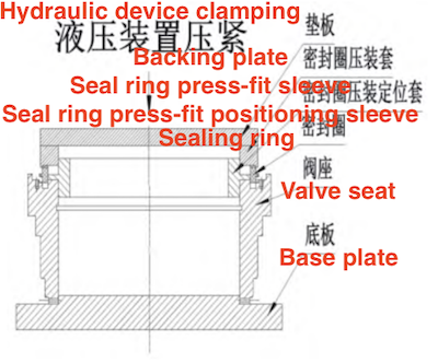
Figure 3 PCTFE Seal Ring Press Diagram
Figure 3 PCTFE Seal Ring Press Diagram
During the lip ring pressing process, uneven installation of the lip ring can easily occur, potentially causing pressure damage and seal failure. A guide tool is necessary when installing the valve seat and valve body to ensure the lip ring is installed reliably and effectively. The installation process is shown in Figure 4 and Figure 5.
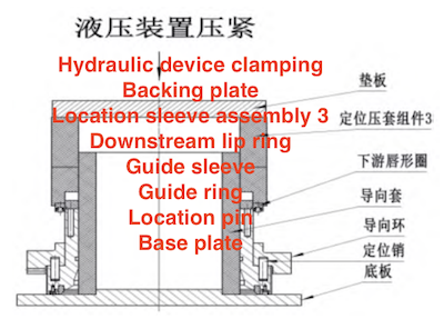
Figure 4 Lip seal ring press
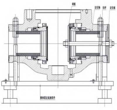
Figure 5 Valve seat and lip ring assembly guide
Figure 4 Lip seal ring press
Figure 5 Valve seat and lip ring assembly guide
Uneven control of the preload force during the preloading of the valve seat disc spring can cause the ball to tilt and lead to incorrect installation of the valve stem. Positioning tooling is required to ensure proper centering of the ball and smooth installation of the valve stem and valve bonnet. The installation process is shown in Figure 6.
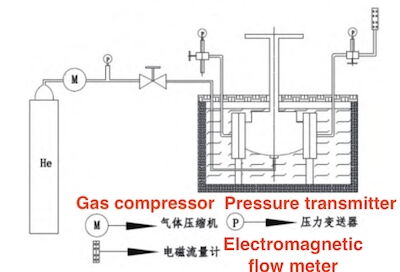
Figure 6 Valve seat disc spring preload installation
Figure 6 Valve seat disc spring preload installation
The installation should be carried out in a dust-free room, with careful attention to cleanliness. All components should be degreased.
When testing high-pressure, large-diameter cryogenic ball valves, the following key points should be noted: before the cryogenic test, helium must be used for gas replacement to prevent water vapor condensation from affecting the valve seal. During the cryogenic test, adequate cooling time is necessary to ensure temperature stability across all valve components. For the SPE-DPE combination valve seat with a DIB-2 structure, the following test plan applies: first, pressurize the upstream valve to the design pressure to check for leaks in the middle cavity and record the upstream pressure transmitter reading, P, once pressure stabilizes. (During pressure maintenance, ensure that the pressure transmitter is connected to the inner cavity of the upstream valve body.) Then, connect the pressure test joint to pressurize the middle cavity, check for downstream leaks, and observe any changes in the upstream pressure gauge as the middle cavity pressure increases slowly. When the upstream pressure gauge starts to rise consistently, stop pressurizing the middle cavity and record the middle cavity test pressure, PZ, allowing the middle cavity pressure to discharge fully to the upstream. When the pressures at both ends balance, PZ reflects the middle cavity's overpressure discharge point.
The schematic diagram is shown in Figure 7 below:
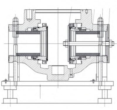
Figure 7 DIB-2 cryogenic ball valve middle cavity self-decompression test scheme
The schematic diagram is shown in Figure 7 below:
Figure 7 DIB-2 cryogenic ball valve middle cavity self-decompression test scheme
This paper provides a comprehensive summary and analysis of key technologies for high-pressure cryogenic ball valves in LNG devices, focusing on critical aspects of processing technology control, assembly process control, and product performance testing. The design scheme for the sealing structure, which impacts valve sealing reliability and service life, is summarized, providing a reliable, prototype-verified design method for the sealing structure of this type of valve. The key control points in processing technology during the prototype manufacturing process are summarized, indicating the direction for essential control points in the processing and manufacturing of this type of valve. Key control points that affect sealing performance and service life during assembly, including the guided pressing of the Lipseal lip ring, guided installation of the valve seat assembly, and centering of the ball during pre-tightening of the valve seat disc spring, are summarized, offering a reliable installation method to address assembly challenges for this type of valve. Key control points in the testing process, such as air replacement before deep cooling and the self-pressure relief test method for the middle cavity, are also detailed to ensure reliable testing of this type of valve. This summary of key technologies for high-pressure cryogenic ball valves in LNG devices establishes a foundation for future design and manufacturing of these valves and provides technical support for mass production and supply.