Positive Displacement Pump: How It Works, Types and Uses
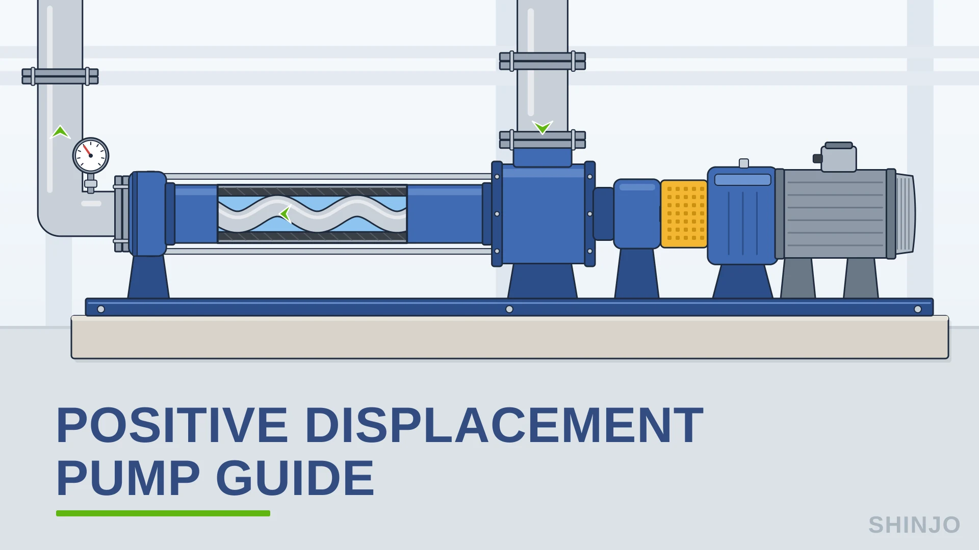
A positive displacement pump traps a fixed volume of liquid and pushes it out with each stroke or shaft revolution (U.S. Department of Energy & Hydraulic Institute, 2006). A US Department of Energy and Hydraulic Institute sourcebook calls this a "collapsing volume" action: the pump squeezes liquid by shrinking the space that holds it (U.S. Department of Energy & Hydraulic Institute, 2006). So flow follows speed, while the system's resistance sets the pressure (U.S. Department of Energy & Hydraulic Institute, 2006). Delivered flow equals displacement times speed times volumetric efficiency (Gaydon, 2022; Hydraulic Institute, n.d.); the shortfall is slip, the pump's internal leakage (Gaydon, 2022). Slip grows with differential pressure and shrinks as viscosity increases (Blodgett, n.d.). Delivered flow therefore falls as pressure climbs, and the loss is largest with thin liquids.
This guide is for procurement, project and maintenance engineers choosing or specifying a PD pump. Specifying one means choosing the family (reciprocating, rotary or controlled-volume metering) and the standard that goes with it, constant or variable displacement, relief protection and the flow-control method, the suction margin (NPIP and acceleration head) and dry-run protection, then checking whether a centrifugal pump fits the duty better.
- A positive displacement pump, or PD pump, traps and moves a fixed volume per stroke or revolution, less slip.
- Delivered flow is displacement times speed times volumetric efficiency. Slip (internal leakage) rises with pressure and falls with viscosity.
- Worked example: 1.0 L/rev at 400 r/min delivers 22.1 m3/h (97.2 US gpm) at 92% volumetric efficiency.
- The Hydraulic Institute (HI) names three PD families: reciprocating, rotary and controlled-volume metering, itself a reciprocating design.
- Never throttle the discharge to control flow. HI calls a relief valve mandatory on reciprocating power pumps, placed ahead of any other valve.
- Example acceleration head: 1.9 m (6.2 ft) on a triplex suction line, 0.3 m with a dampener.
- For viscous fluids both types can handle, HI says PD is often 10 to 40 points more energy-efficient than centrifugal.
- Abstract
- Key Takeaways
- Positive displacement pump definition
- Glossary
- How does a positive displacement pump work?
- Types of positive displacement pump and their standards
- Constant displacement pump vs variable displacement pump
- Relief valves and flow control on a PD pump
- Suction: NPIP, acceleration head and pulsation
- By the Numbers
- Centrifugal vs positive displacement pump: how to choose
- Downsides and dry running of positive displacement pumps
- Specifying a positive displacement pump
- Frequently Asked Questions
- Conclusion
- References
A positive displacement pump (PD pump) traps a fixed volume of liquid in a chamber and forces that volume into the discharge line with each stroke or shaft revolution (U.S. Department of Energy & Hydraulic Institute, 2006). Its flow follows its speed, and its discharge pressure is whatever the system's resistance demands (U.S. Department of Energy & Hydraulic Institute, 2006). Delivered flow is the displaced volume less any internal leakage, called slip (Gaydon, 2022).
Per the Hydraulic Institute (HI) Data Tool, "Positive displacement pumps are a class which trap and move a volume of fluid with each shaft rotation" (Hydraulic Institute, 2024).
HI divides that class into reciprocating types, which use pistons, plungers and diaphragms, and rotary types, which use meshing components such as screws, gears, lobes and vanes (Hydraulic Institute, 2024). Rotodynamic pumps work differently. They impart energy to the liquid through a rotating impeller, propeller or rotor (Hydraulic Institute, 2024).
The U.S. Department of Energy and Hydraulic Institute pumping sourcebook (2nd edition, 2006) says PD pumps "pressurize fluid with a collapsing volume action" (U.S. Department of Energy & Hydraulic Institute, 2006) and "have a fixed displacement volume. Consequently, the flow rates they generate are directly proportional to their speed. The pressures they generate are determined by the system's resistance to this flow" (U.S. Department of Energy & Hydraulic Institute, 2006).
An HI overview of the technology, published in Plant Services, states the consequence: "PD pumps, at constant speed, are constant-flow devices, whereas centrifugal pumps are variable-flow devices" (Hydraulic Institute PD Pump Members, 2011). To define positive displacement pump operation in one sentence, the screw-pump maker KRAL puts the contrast this way: a centrifugal pump creates pressure and flow results, while a positive displacement design creates flow and pressure results.
Constant flow is an approximation. A common shorthand says the flow stays the same regardless of pressure, and that overstates it. An HI article on viscosity words it more carefully: the pump displaces a certain volume with every revolution of the shaft, "minus any volumetric leakage (slip)" (Gaydon, 2022). Slip grows as differential pressure rises, so delivered flow falls as discharge pressure climbs (Blodgett, n.d.). A more viscous liquid reduces slip and raises volumetric efficiency (Gaydon, 2022). Clearances and wear change it too (Blodgett, n.d.).
The name describes the mechanism. "Positive" refers to how the liquid is handled: it is enclosed in a shrinking space and forced out, rather than accelerated by a spinning impeller. The DOE sourcebook says the pumps "squeeze fluid by decreasing the volume that contains it" (U.S. Department of Energy & Hydraulic Institute, 2006). In practice, a flow figure for this kind of pump means little unless it states the speed, the differential pressure and the liquid viscosity it applies to.
- Slip: internal leakage flow, the difference between the theoretical and the actual volume per shaft revolution (Gaydon, 2022).
- Volumetric efficiency: the actual volume per shaft revolution over the theoretical volume per revolution (Gaydon, 2022).
- Rotodynamic pump: a pump, such as a centrifugal pump, that imparts energy to the liquid through a rotating impeller, propeller or rotor (Hydraulic Institute, 2024).
- Constant displacement pump: a positive displacement pump whose volume per revolution is fixed by design (Gannon, n.d.); fixed displacement means the same thing.
- Variable displacement pump: a pump that can change its volume per revolution while it runs (Gannon, n.d.).
- Controlled-volume metering pump (CVMP): a reciprocating positive displacement pump configured to dispense an accurate volume of liquid during a specified time period (Hydraulic Institute PD Pump Members, 2011).
- Deadheading: running a pump against a closed discharge.
- NPIP: net positive inlet pressure, "the absolute pressure required at the inlet of the pump to prevent cavitation"; NPIPA is what the system supplies, NPIPR what the pump requires (Viking Pump, n.d.).
- Acceleration head: inlet pressure a reciprocating pump loses (Henshaw, n.d.) as its pulsing suction flow speeds up and slows down with each stroke.
A positive displacement pump works by trapping a fixed volume of liquid and forcing it out of the discharge with each stroke or shaft revolution (U.S. Department of Energy & Hydraulic Institute, 2006). Its delivered flow is set by that displacement and the speed, less an internal leakage called slip (Gaydon, 2022), while the system's resistance sets the pressure (U.S. Department of Energy & Hydraulic Institute, 2006).
Inside a reciprocating PD pump, a moving piston forces liquid out of a closed cylinder through inlet and outlet valves (Hydraulic Institute PD Pump Members, 2011). In a rotary pump, a rotating element inside a pumping chamber drives the liquid, and there are no inlet or discharge valves (Hydraulic Institute PD Pump Members, 2011).
The simplest way to explain positive displacement pump behavior is one line of arithmetic. For controlled-volume metering pumps, the Hydraulic Institute (HI) writes it as "Rate of flow = Displacement x Cycles per unit of time x Volumetric efficiency" (Hydraulic Institute, n.d.). HI defines volumetric efficiency as the actual volume per shaft revolution over the theoretical volume per revolution; the difference is leakage flow known as slip (Gaydon, 2022). Theoretical capacity is directly proportional to speed (Gaydon, 2022).
HI states that internal slip is affected by viscosity and pressure (Gaydon, 2022), and that higher viscosity "reduces the amount of slip and increases the volumetric efficiency" (Gaydon, 2022). Blodgett, writing in Pumps & Systems, states that slip does not increase with speed, so a rotary pump gains volumetric efficiency as it runs faster, though faster running brings abrasive wear, shear and, with very viscous liquids, incomplete cavity filling (Blodgett, n.d.). Slip does rise with differential pressure, more so with flexible or compressible parts, and it depends on clearances and wear (Blodgett, n.d.).
Shinjo's G-type single-screw pump table lists the G20-1 at 960 r/min delivering 0.96 m3/h (4.2 US gpm) at 0.3 MPa (43.5 psi) and 0.8 m3/h (3.5 US gpm) at 0.6 MPa (87 psi). Same pump, same speed: the flow lost at the higher pressure is extra slip.
Viscosity can change slip by a wide margin. In one manufacturer's 2014 test of a single rubber-lobed rotary lobe pump at 300 r/min and 25 psi (1.7 bar) differential, slip was 24.5% of the displaced quantity on a 1 cP liquid and 2.8% on a 401 cP liquid (Blodgett, n.d.). The figures describe that one pump only.
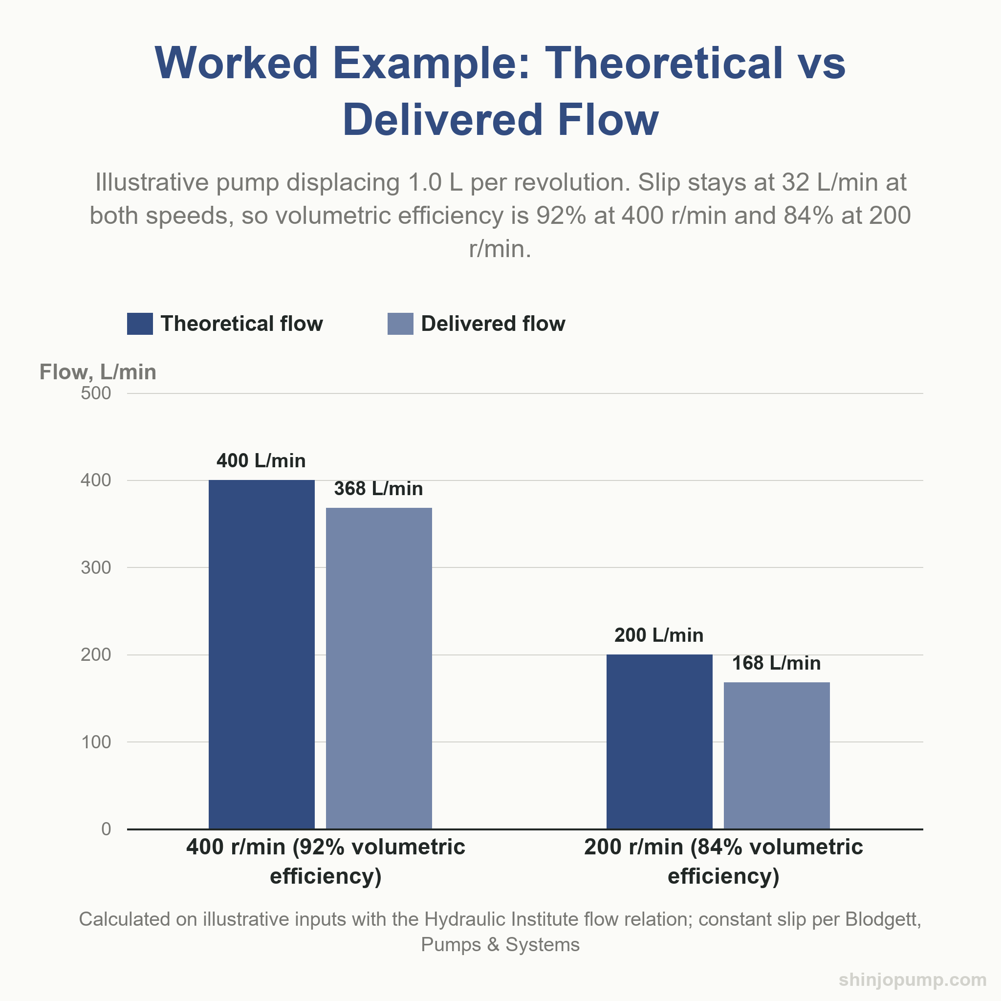
Take a displacement pump of 1.0 L (61.0 in3) per revolution at 400 r/min; the inputs are illustrative, not a Shinjo model. Theoretical flow is 400 L/min, or 24.0 m3/h (105.7 US gpm). Assuming 92% volumetric efficiency, the pump delivers 368 L/min, or 22.1 m3/h (97.2 US gpm). Slip is the 32 L/min difference, 1.92 m3/h (8.5 US gpm).
At 200 r/min against the same pressure and liquid, slip is held at 32 L/min, since slip does not rise with speed (Blodgett, n.d.). Theoretical flow halves to 200 L/min while delivered flow falls to 168 L/min, or 10.08 m3/h (44.4 US gpm). Volumetric efficiency drops from 92% to 84%.
| Quantity | At 400 r/min | At 200 r/min |
|---|---|---|
| Theoretical flow | 400 L/min | 200 L/min |
| Delivered flow | 368 L/min | 168 L/min |
| Slip | 32 L/min | 32 L/min |
| Volumetric efficiency | 92% | 84% |
Real slip also depends on pressure, viscosity, wear and clearances. HI states that theoretical horsepower is proportional to speed and pressure (Gaydon, 2022). The delivered 368 L/min is 0.006133 m3/s; at 10 bar (145 psi) differential, hydraulic power is 0.006133 m3/s x 1,000,000 Pa = 6.13 kW (8.2 hp) before mechanical and volumetric losses.
HI advises consulting the manufacturer on viscous performance (Hydraulic Institute, n.d.), so a PD pump inquiry should ask for delivered flow at the duty's differential pressure and viscosity.
The Hydraulic Institute (HI) PD Pump Members name three major categories of positive displacement pump: reciprocating, rotary and the controlled-volume metering pump (CVMP) (Hydraulic Institute PD Pump Members, 2011). HI's Data Tool divides the same class into two, reciprocating and rotary (Hydraulic Institute, 2024). Both counts are correct. HI describes metering pumps as "reciprocating positive-displacement pumps configured to dispense an accurate volume of liquid during a specified time period" (Hydraulic Institute PD Pump Members, 2011), so the third category sits inside the first. The split still matters to a buyer, because the standards follow it.
| Family | Examples | Standards (current edition) |
|---|---|---|
| Reciprocating power | Piston and plunger power pumps, simplex to multiplex (Hydraulic Institute, 2024) | HI 6.1-6.5-2015, reaffirmed 2020; API 674 3rd ed. 2010, reaffirmed 2026; ISO 13710:2004, confirmed 2026 |
| Air-operated (reciprocating) | Air-operated diaphragm and bellows pumps (Hydraulic Institute, 2024) | ANSI/HI 10.1-10.5 (2021) (Hydraulic Institute, 2024) |
| Controlled-volume metering | Diaphragm and piston metering pumps (Hydraulic Institute, 2024) | ANSI/HI 7.1-7.5-2023; API 675 3rd ed. 2012, reaffirmed 2021 |
| Rotary | Gear, lobe, vane, screw, peristaltic, circumferential piston and axial piston pumps (Hydraulic Institute, 2024) | ANSI/HI 3.1-3.5-2021; ANSI/HI 3.6 rotary pump tests (2022); API 676 4th ed. 2022; ISO 14847:1999 (currently under systematic review) |
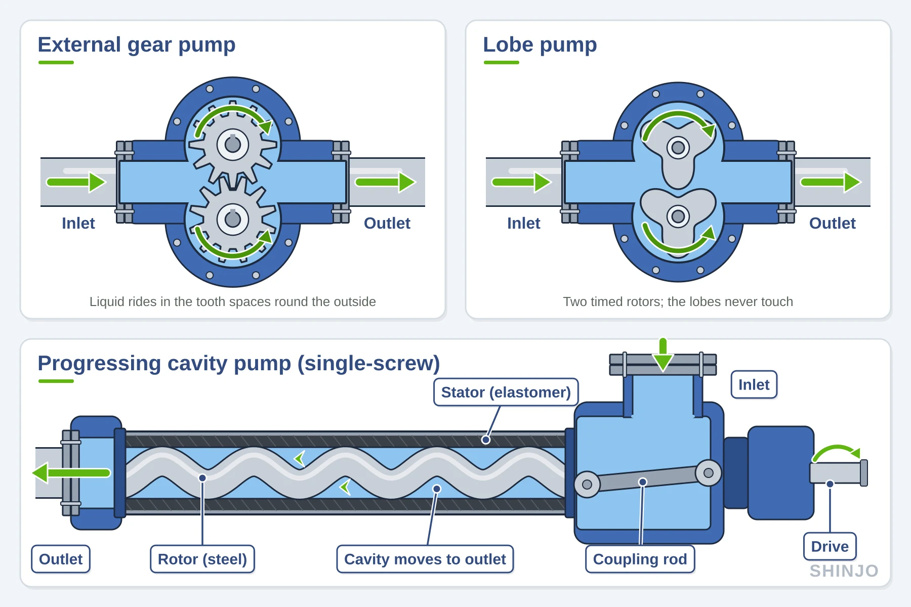
A reciprocating PD pump moves liquid with a piston, plunger or diaphragm (Hydraulic Institute, 2024). HI files air-operated diaphragm pumps under reciprocating (Hydraulic Institute, 2024), with their own standard, ANSI/HI 10.1-10.5 (Hydraulic Institute, 2024). API 674 covers reciprocating pumps for petroleum, chemical and gas industry services and excludes controlled-volume, hydraulically driven and rotary pumps. ISO 13710 does not apply to controlled-volume or rotary pumps either, and ISO confirmed its 2004 edition in 2026.
Shinjo's diaphragm range belongs to this family: Shinjo lists air-operated QBY and motor-driven DBY models.
HI's Data Tool lists external and internal gear, single and three lobe, flexible and sliding vane, circumferential piston, flexible tube (peristaltic), and screw pumps in single-screw (progressing cavity), two-screw (timed) and three-screw (untimed) forms (Hydraulic Institute, 2024). It also places the axial piston pump under rotary, not reciprocating (Hydraulic Institute, 2024). API 676 covers rotary process pumps and excludes controlled-volume, hydraulically driven and reciprocating pumps. ISO 14847:1999 (currently under systematic review) sets technical requirements for rotary positive displacement pumps.
The screw pumps Shinjo lists are single-screw (progressing cavity) designs. Shinjo describes its G type as a rotary displacement pump whose main working parts are an eccentric screw (rotor) and a fixed bush (stator). Shinjo lists 0.6 MPa (87 psi) outlet pressure for a single-stage G type and 1.2 MPa (174 psi) for a dual-stage one, each added stage contributing 0.6 MPa. Shinjo's range also includes a gear oil pump.
ANSI/HI 7.1-7.5-2023 treats controlled-volume metering pumps, also called proportioning, chemical injection, chemical feed or dosing pumps, as reciprocating pumps for chemical injection, proportional blending or metered transfer. API 675 covers reciprocating controlled-volume pumps of hydraulic-diaphragm or packed-plunger design; rotary positive displacement pumps and diaphragm pumps that use direct mechanical actuation are excluded.
API's positive displacement pump standards for the petroleum, chemical and gas industries line up with HI's three categories: API 674 (3rd edition, 2010, reaffirmed 2026) for reciprocating pumps, API 675 (3rd edition, 2012, reaffirmed 2021) for controlled-volume metering pumps and API 676 (4th edition, 2022) for rotary pumps. Both API 674 and API 676 exclude controlled-volume pumps.
At a fixed speed, a screw pump delivers less flow as differential pressure rises, and the loss is larger on a thin liquid, so a flow figure on a quote means little without the pressure and viscosity it applies to. Shinjo quotes its screw pump range against a stated duty point: send the liquid, its viscosity at the lowest pumping temperature, the flow you need and the differential pressure, and ask for delivered flow at that duty. See Shinjo’s screw pumps
A constant displacement pump is a positive displacement pump whose volume per revolution is fixed by design; a variable displacement pump can change that volume while it runs (Gannon, n.d.). "Constant displacement" is the hydraulics term, and fixed displacement means the same thing.
Mobile Hydraulic Tips notes that a fixed pump's displacement does not change "regardless of how the pump is controlled or what occurs downstream" (Gannon, n.d.). HK Hydraulik's glossary puts the result in flow terms: a constant pump delivers "a virtually constant volume flow at a given speed," and "the actual volume flow depends directly on the speed of the drive motor". Mobile Hydraulic Tips adds: "If you need less flow than the pump is rated for, the excess flow must be diverted or relieved to tank" (Gannon, n.d.). Panagon Systems, a hydraulic pump remanufacturer, names external and internal gear pumps as fixed-displacement examples and says vane and piston pumps can also be fixed.
A variable displacement pump changes its displacement manually, hydraulically or electronically (Gannon, n.d.). In a variable axial piston pump, the swashplate angle sets piston stroke, and a pressure compensator reduces that angle when downstream pressure exceeds its setting (Gannon, n.d.). Variable vane pumps shift the cam ring instead (Gannon, n.d.). That flexibility adds mechanism, and Panagon describes variable displacement pumps as more complex. The difference is where surplus flow goes: a compensated pump trims its own output, while a fixed pump needs an external path for it.
In process duty, gear, lobe and screw pumps have a fixed displacement volume, so flow from such a PD pump is changed by speed or by bypass (Hydraulic Institute PD Pump Members, 2011; U.S. Department of Energy & Hydraulic Institute, 2006). Shinjo, for example, states that flow on its G type single screw pump is adjusted "by changing the speed", and its screw, diaphragm and gear pump pages list no variable-displacement model.
On the process side, variable displacement appears in the controlled-volume metering pump, a reciprocating positive displacement pump that varies its effective displacement through stroke length (Hydraulic Institute, n.d.; Hydraulic Institute PD Pump Members, 2011). The Hydraulic Institute says flow against stroke-length setting is linear but "not necessarily proportional in that 50% stroke setting may not equal 50% flow" (Hydraulic Institute, n.d.).
Closing a discharge valve does not cut the flow of a positive displacement pump; pressure rises instead. With all downstream valves closed, the US Department of Energy (DOE) says pressure builds "until a relief valve lifts, a pipe or fitting ruptures, or the pump motor stalls" (U.S. Department of Energy & Hydraulic Institute, 2006).
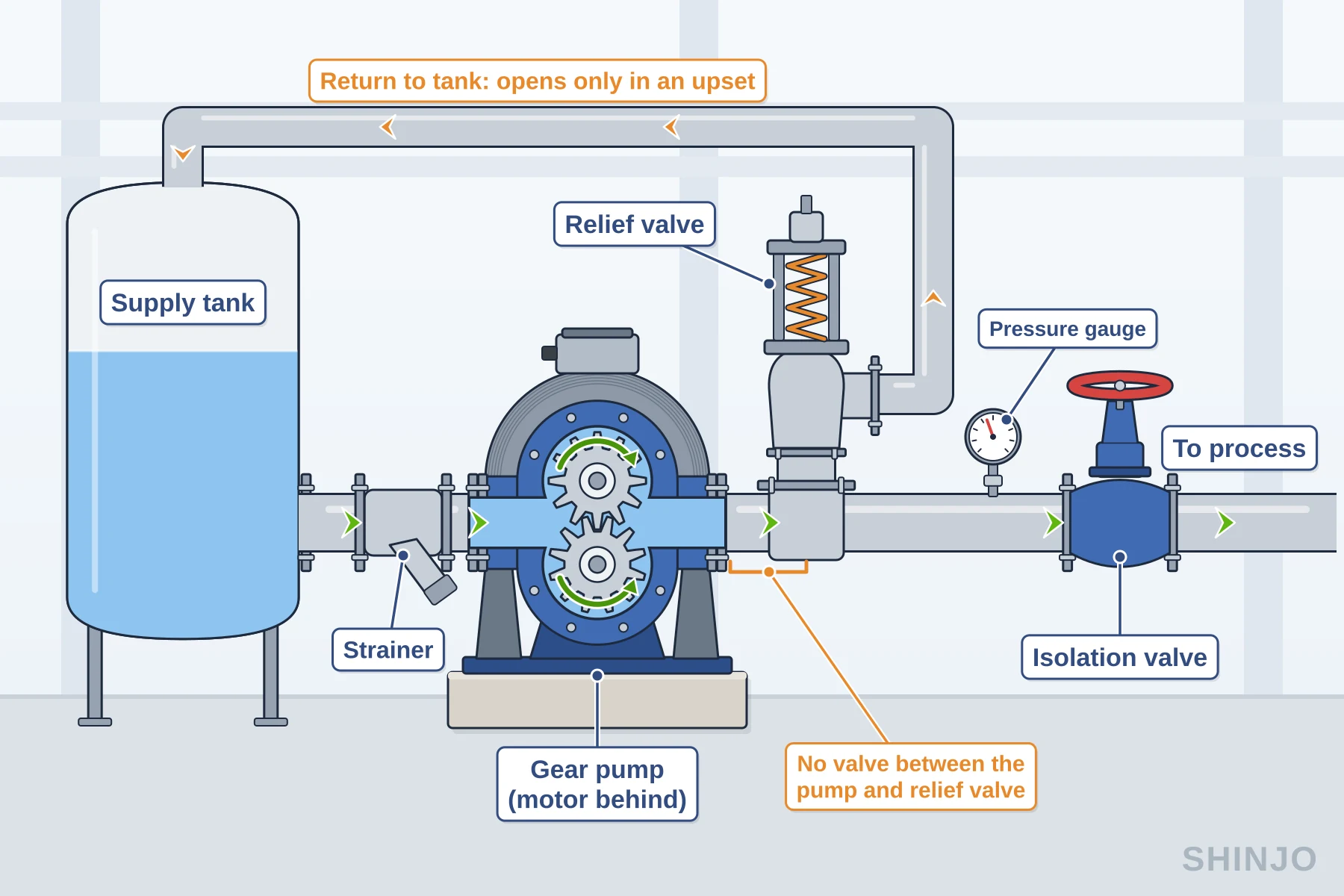
Throttling a PD pump gives no flow control either. Pressure rises, and delivered flow falls only by the added slip (Blodgett, n.d.; U.S. Department of Energy & Hydraulic Institute, 2006). DOE warns that relying on relief valves "adds an element of risk" (U.S. Department of Energy & Hydraulic Institute, 2006), and Viking Pump states that pressure relief valves are neither flow control valves nor pressure regulators (Hall, n.d.). Viking adds that they are there only to prevent overpressure in an upset (Hall, n.d.).
For reciprocating power pumps, the Hydraulic Institute (HI) calls a discharge relief valve mandatory (Hydraulic Institute, n.d.). Sized for the pump's flow and set to open above the operating discharge pressure, it belongs in the discharge line close to the pump, ahead of any other valves (Hydraulic Institute, n.d.). Spring-loaded valves usually need 10% to 25% above set pressure to open fully, depending on spring design (Hydraulic Institute, n.d.).
Viking Pump says rotary positive displacement pumps such as gear and lobe designs must have overpressure protection (Hall, n.d.). For its pumps with internal relief valves, Viking says cracking pressure can be set 10% to 15% above maximum differential pressure (Viking Pump, n.d.). Viking's figure marks the start of opening; HI's 10% to 25% is the further rise to fully open (Hydraulic Institute, n.d.).
Viking names three valve types: internal, which returns liquid to the pump inlet and can heat it in long full bypass; return-to-tank, which carries heat away; and inline, in the system piping (Hall, n.d.), with no isolation valve between it and the pump (Hall, n.d.). Flammable liquids may need return-to-tank valves, since a deadheaded pump (one running against a closed discharge) on internal relief could heat them past their flash point (Hall, n.d.). DOE notes that relief valves, internal in many positive displacement pumps (U.S. Department of Energy & Hydraulic Institute, 2006), need periodic testing and maintenance (U.S. Department of Energy & Hydraulic Institute, 2006).
Viking also notes an exception: most air-operated double diaphragm (AODD) pumps can be deadheaded without overpressure protection, because maximum discharge pressure cannot exceed the air inlet pressure, usually 100 psi (7 bar) or less (Hall, n.d.). Shinjo lists a 0.3 to 0.7 MPa (44 to 102 psi) air supply for its QBY and QBK air-operated diaphragm pumps. Check the data sheet before deadheading a given pump.
Flow from a PD pump is directly proportional to speed (U.S. Department of Energy & Hydraulic Institute, 2006), so a variable frequency drive (VFD) changes flow by changing speed. HI notes that the torque load stays constant as speed falls, unlike on a rotodynamic pump (Hydraulic Institute, n.d.), and that start-up can demand maximum pressure and torque (Hydraulic Institute, n.d.); select the drive for both. On metering pumps, stroke length also sets flow, linearly but not necessarily in proportion, per HI (Hydraulic Institute, n.d.). A bypass back to suction recirculates liquid the way an internal relief valve does, the case in which Viking warns of heating (Hall, n.d.). A control bypass therefore needs its own valve; the relief valve stays reserved for upsets (Hall, n.d.).
Suction on a positive displacement pump is often specified in net positive inlet pressure (NPIP), which Viking Pump defines as "the absolute pressure required at the inlet of the pump to prevent cavitation" and likens to net positive suction head (NPSH) (Viking Pump, n.d.). NPIPA is what the system supplies; NPIPR is what the pump requires (Viking Pump, n.d.). Blacoh notes that these terms "reflect the use of pressure units rather than feet" (Cornell, n.d.).
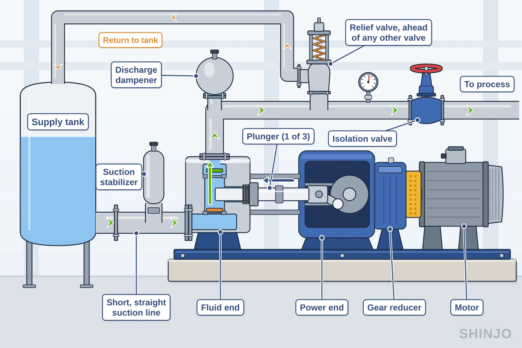
The Hydraulic Institute (HI) states that viscosity raises the NPIPR of PD pumps (Gaydon, 2022). A reciprocating PD pump also loses inlet pressure to acceleration head (Henshaw, n.d.), because it draws in pulses and the suction flow speeds up and slows down with each stroke. Peak flow from a piston or diaphragm pump "can be as much as 3.14 times the average or mean flow," per Blacoh (Cornell, n.d.); HI's metering-pump guidance says peaks can reach three times the average (Hydraulic Institute, n.d.). For short metering-pump runs, HI's rule of thumb is suction piping one size above the discharge piping, or two sizes above the pump suction connection (Hydraulic Institute, n.d.).
The acceleration-head equation in HI standards uses US units: ha = (L × V × N × C) / (k × g) (Cornell, n.d.; Henshaw, n.d.). Here ha is in ft, L is the actual (not equivalent) suction length in ft, V the average suction velocity in ft/s, N the crankshaft speed in rpm and g = 32.2 ft/s² (Henshaw, n.d.). C is 0.400 for a single-acting simplex, 0.066 for a triplex and 0.022 for a nonuplex; k is 1.5 for most liquids (Henshaw, n.d.). A properly selected dampener cuts the effective L to about 10 pipe diameters (Henshaw, n.d.). The equation is recommended only for relatively short, non-elastic suction lines (Henshaw, n.d.).
Using the HI equation, a triplex plunger pump on a 3.05 m (10 ft) suction line at 0.457 m/s (1.5 ft/s) and 300 rpm loses 1.87 m (6.15 ft) to acceleration head, or 0.18 bar (2.7 psi) for water at specific gravity 1.0. With a suction dampener on a DN50 (NPS 2) line, that drops to 0.31 m (1.0 ft).
Before comparing NPIPA with NPIPR on a reciprocating PD pump, subtract the acceleration head. The equation is written for the pulsing suction flow of a reciprocating pump (Henshaw, n.d.). On a rotary positive displacement pump, check NPIPR at the duty viscosity, since viscosity raises it (Gaydon, 2022).
- 3.14x peak-to-mean flow ratio a piston or diaphragm pump can reach, per Blacoh (Cornell, n.d.)
- ~10 diameters effective suction length with a properly selected dampener, per HI (Henshaw, n.d.)
- 1.87 m acceleration head in the triplex worked example above, calculated with the HI equation, no dampener
- 0.31 m the same triplex with a dampener on a DN50 line
The search "centrifugal positive displacement pump" asks for a comparison, and the answer turns on viscosity, pressure and flow control. The US Department of Energy sourcebook says centrifugal pumps are more common because they are simple and safe, need minimal maintenance and suffer less wear (U.S. Department of Energy & Hydraulic Institute, 2006). The same sourcebook points to a positive displacement pump for high pressure at low flow, high viscosity, accurately controlled flow, self-priming and low-shear duties, and wherever pump efficiency is highly valued (U.S. Department of Energy & Hydraulic Institute, 2006).
Viscosity separates the two families first. The Hydraulic Institute (HI) PD pump members report that frictional losses degrade centrifugal flow and efficiency with fluids above 500 SSU (Saybolt seconds universal) (Hydraulic Institute PD Pump Members, 2011), while rotary PD flow and efficiency typically increase with viscosity (Hydraulic Institute PD Pump Members, 2011). A 2025 review of the literature reports centrifugal head losses of 8 m (26 ft) or more and an efficiency reduction of 20% as viscosity approaches 800 to 1,000 cP (Ifidon et al., 2025). HI bases its ANSI/HI 9.6.7 correction factors on empirical data up to 3,000 cSt, usable to 4,000 cSt with increased uncertainty, and notes they do not apply to PD pumps (Hydraulic Institute, n.d.). Shinjo's guide on how to select a centrifugal pump sets out that correction method.
Small flows at high pressure also favor a positive displacement pump. HI's PD pump members write that PD technology "easily handles flows below 100 gpm and pressures greater than 200 psi" (Hydraulic Institute PD Pump Members, 2011), roughly 22.7 m3/h and 13.8 bar. PD pumps handle a high percentage of entrained air or gas (Hydraulic Institute PD Pump Members, 2011; U.S. Department of Energy & Hydraulic Institute, 2006) and are self-priming with excellent suction lift (Hydraulic Institute PD Pump Members, 2011). Because they are constant-torque devices, a variable frequency drive (VFD) on one must be rated for that load (Hydraulic Institute PD Pump Members, 2011).
To tell the two apart, look at parts and curves. A rotary PD pump has meshing gears, lobes, screws or vanes and no impeller (Hydraulic Institute, 2024). On a data sheet, PD flow stays nearly flat as pressure rises, while centrifugal flow falls as head rises (Hall, n.d.; Hydraulic Institute PD Pump Members, 2011). Never test by closing the discharge valve.
| Factor | Centrifugal | Positive displacement |
|---|---|---|
| Flow vs pressure | Flow falls as head rises (Hall, n.d.; Hydraulic Institute PD Pump Members, 2011) | Flow stays nearly flat at constant speed (Hall, n.d.; Hydraulic Institute PD Pump Members, 2011) |
| Viscosity | Flow and efficiency degrade above 500 SSU (Hydraulic Institute PD Pump Members, 2011) | Rotary types: flow and efficiency typically rise with viscosity (Hydraulic Institute PD Pump Members, 2011) |
| Efficiency on viscous fluids | Near 80% on water, about 50% at 1,000 SSU (SG 0.9), in HI's worked example (Gaydon, 2022) | Often 10 to 40 points higher, for viscous fluids that both can handle (Hydraulic Institute PD Pump Members, 2011) |
| Entrained gas | Depends on the design; check the data sheet | Handles a high percentage of air or gas (Hydraulic Institute PD Pump Members, 2011; U.S. Department of Energy & Hydraulic Institute, 2006) |
| Priming and suction lift | Often needs equipment to remove gas and prime the impeller; some designs are self-priming (U.S. Department of Energy & Hydraulic Institute, 2006) | Self-priming, with excellent suction lift (Hydraulic Institute PD Pump Members, 2011) |
| Flow control | Valve or speed; a variable-torque load on a VFD (Hydraulic Institute, n.d.) | Speed, through a VFD rated for constant torque (Hydraulic Institute PD Pump Members, 2011) |
| Overpressure protection | May not need it (Hall, n.d.) | Needed, usually a relief valve (U.S. Department of Energy & Hydraulic Institute, 2006); most AODD pumps aside (Hall, n.d.) |
| Best-fit duty | Thin liquids at higher flow; simple, safe, low wear (U.S. Department of Energy & Hydraulic Institute, 2006) | Viscous, high-pressure low-flow, metering and low-shear duties (U.S. Department of Energy & Hydraulic Institute, 2006) |
For viscous fluids that both pump types can handle, the Hydraulic Institute's PD pump members say the positive displacement option often can be 10 to 40 points more energy-efficient than the centrifugal pump (Hydraulic Institute PD Pump Members, 2011). In HI's worked example, one centrifugal pump fell from near 80% efficiency on water to approximately 50% on 1,000 SSU (Gaydon, 2022).
HI frames that advantage around viscous fluids, so it gives no efficiency reason to prefer PD on water. The example liquid, roughly 216 cSt, sits well inside the ANSI/HI 9.6.7 data range, so the loss of about 30 points came at a moderate viscosity. For thin liquids at higher flow, start with a centrifugal pump. For viscous duties, correct its curve and compare a PD pump at the same duty point, relief protection and wear parts included.
The fixed displacement that makes a PD pump predictable also makes it demanding to protect. The US Department of Energy pumping sourcebook says PD pumps "typically require more system safeguards, such as relief valves" (U.S. Department of Energy & Hydraulic Institute, 2006). The Hydraulic Institute adds that they require some type of pressure protection and that certain designs require pulsation control (Hydraulic Institute PD Pump Members, 2011). Some units also carry duty-cycle limits (Hydraulic Institute PD Pump Members, 2011).
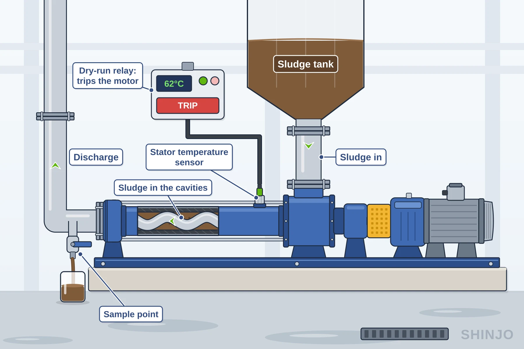
Wear is the second trade-off, and the same sourcebook lists the mechanisms. Cyclical action "causes fatigue in components such as bearings and diaphragms" (U.S. Department of Energy & Hydraulic Institute, 2006). Pulsating flow creates vibration that hastens degradation of piping, valves and supports, especially when pulse rate harmonics coincide with a natural frequency (U.S. Department of Energy & Hydraulic Institute, 2006); accumulators can dampen it (U.S. Department of Energy & Hydraulic Institute, 2006). PD pumps "are very susceptible to wear from abrasives" (U.S. Department of Energy & Hydraulic Institute, 2006). For rotary pumps, the Hydraulic Institute says close running clearances make clean piping a must: dirt, grit, weld bead or scale "will damage and may seize the pump" (Hydraulic Institute, n.d.). A relatively high number of moving parts means larger spare-parts inventories (U.S. Department of Energy & Hydraulic Institute, 2006) and, in the sourcebook's words, "higher maintenance requirements than other types" (U.S. Department of Energy & Hydraulic Institute, 2006).
Whether a positive displacement pump can run dry depends on its type.
Progressing cavity pumps are one of the types at risk. A 2024 NETZSCH article says these pumps "can be sensitive to dry running if not sufficiently lubricated, leading to increased wear" (NETZSCH Pumps & Systems, 2024).
Penn Valley Pump, a vendor of double disc pumps, lists gear, rotary lobe and piston or plunger pumps among the types not to run dry, and says "most positive displacement pumps can only run dry for a few minutes before friction heats up the internals".
An air-operated double diaphragm pump tolerates dry running, but Yamada treats that ability as protection against an upset, not an operating strategy: a pump running dry cycles faster, adding diaphragm wear and wasting compressed air (Eklund, 2026). Diaphragm does not mean dry-run tolerant, though: Shinjo states that its DBY electric diaphragm pump "is strictly forbidden to run dry". NETZSCH's glossary entry on dry running says some displacement pumps, such as peristaltic pumps, can tolerate dry running without damage, while others need dry-running sensors or automatic shutdowns. Confirm the rating on the model's data sheet, and where a suction tank can empty, specify dry-run protection.
A usable inquiry for a positive displacement pump states the liquid, duty, suction and protection, with units and operating conditions. Give viscosity at the coldest condition: the Hydraulic Institute bases rotary pump pipe size on the required flow, velocity limits, "the fluid viscosity at the lowest pumping temperature", piping length and pump elevation (Hydraulic Institute, n.d.).
| Item | What to state | Why it matters |
|---|---|---|
| Liquid | Name, specific gravity, viscosity range | Viscosity shifts slip and input power (Gaydon, 2022) |
| Duty | Flow at the duty, differential pressure, maximum discharge pressure | Sets size, speed, power and relief setting |
| Suction | NPIPa, or suction layout and line length | Checked against the pump's NPIPr |
| Solids and shear | Particle size, concentration, abrasiveness, shear sensitivity | Higher speed adds abrasive wear and shear (Blodgett, n.d.) |
| Temperature and materials | Operating range; wetted metals and elastomers | Compatibility changes with liquid and temperature |
| Seal | Packing, mechanical seal or sealless | Must suit liquid, pressure and temperature |
| Drive | Motor, speed range, VFD | A positive displacement pump is a constant-torque load; rate the VFD for it (Hydraulic Institute PD Pump Members, 2011) |
| Relief | Internal, return-to-tank or inline; set pressure | Internal relief recirculates to the inlet and can heat the liquid (Hall, n.d.) |
| Pulsation | Dampener needed, and who supplies it | Pulsation vibration wears piping, valves and supports (U.S. Department of Energy & Hydraulic Institute, 2006) |
| Tests and data sheet | ANSI/HI 3.6 rotary or HI 6.6 reciprocating test; the API data sheet where API applies (API 675 carries them in its Annex A) (Ray, n.d.) | Fixes how performance is proven |
For pressure, request five values as Viking Pump defines them: maximum differential pressure, maximum allowable working pressure, maximum allowable inlet pressure, cracking pressure and full bypass pressure (Viking Pump, n.d.). A request for Shinjo's single-screw progressing cavity pumps needs the same data.
API 675 sets steady-state accuracy, linearity and repeatability criteria for controlled-volume metering pumps (Ray, n.d.), and its Annex A data sheets come in USC and SI units (Ray, n.d.). Wanner, for example, states its metering pumps exceed ±1% steady-state accuracy, ±3% linearity and ±3% repeatability, so a metering inquiry should name the standard.
Can you run a PD pump dry?
It depends on the type. Progressing cavity pumps should not; NETZSCH notes they can be sensitive to dry running, which increases wear (NETZSCH Pumps & Systems, 2024). Penn Valley Pump lists piston, plunger, gear and lobe pumps among the types not to run dry either. Air-operated double diaphragm pumps tolerate it, though a pump running dry cycles faster, adding diaphragm wear and wasting compressed air (Eklund, 2026).
Is a screw pump a PD pump?
Yes. The Hydraulic Institute lists screw pumps among rotary positive displacement designs, which move liquid with meshing components such as screws, gears, lobes and vanes (Hydraulic Institute, 2024). Its table names single-screw (progressing cavity), two-screw (timed) and three-screw (untimed) pumps (Hydraulic Institute, 2024).
Is a gear pump a PD pump?
Yes, a rotary one. The Hydraulic Institute's Data Tool lists external gear pumps and internal gear pumps, with or without a crescent, among rotary types (Hydraulic Institute, 2024). Their displacement is fixed, so flow follows shaft speed (U.S. Department of Energy & Hydraulic Institute, 2006), less internal leakage called slip (Gaydon, 2022).
What are the three types of positive displacement pumps?
Hydraulic Institute members name three major categories: reciprocating, rotary and controlled-volume metering pumps (Hydraulic Institute PD Pump Members, 2011). Metering pumps are reciprocating designs configured to dispense an accurate volume in a set time (Hydraulic Institute PD Pump Members, 2011). The Institute's Data Tool divides the class into just two, reciprocating and rotary, so sources group them differently (Hydraulic Institute, 2024).
What is the difference between positive and non-positive displacement pumps?
A PD pump traps a volume of liquid and moves it with each shaft rotation (Hydraulic Institute, 2024), without relying on a velocity change (Hydraulic Institute PD Pump Members, 2011). The non-positive kind is the rotodynamic pump, such as a centrifugal pump, which imparts energy to the liquid with a rotating impeller (Hydraulic Institute, 2024).
How to tell if a pump is centrifugal or positive displacement?
A centrifugal pump spins an impeller; a positive displacement design uses pistons, plungers, diaphragms or meshing parts such as gears and screws (Hydraulic Institute, 2024). At constant speed, PD flow stays nearly flat as head rises, while centrifugal flow falls (Hydraulic Institute PD Pump Members, 2011). Never test by closing the discharge: a PD pump keeps building pressure (U.S. Department of Energy & Hydraulic Institute, 2006).
Why is it called a positive displacement pump?
The name describes the mechanism. The pump encloses a volume of liquid and positively forces it out by shrinking the space that contains it (U.S. Department of Energy & Hydraulic Institute, 2006). The US Department of Energy calls this a collapsing volume action, squeezing out the displacement volume with each piston stroke or shaft rotation (U.S. Department of Energy & Hydraulic Institute, 2006).
Why use a VFD on a pump?
On a positive displacement pump, flow is typically varied by speed, which a variable frequency drive (VFD) controls (Hydraulic Institute PD Pump Members, 2011; U.S. Department of Energy & Hydraulic Institute, 2006); throttling the discharge raises pressure rather than cutting flow (U.S. Department of Energy & Hydraulic Institute, 2006). Rate the drive for a constant-torque load: a PD pump keeps that load as speed falls, unlike a rotodynamic pump (Hydraulic Institute, n.d.).
A positive displacement pump moves a fixed volume with every stroke or revolution, less the slip that leaks back inside it. Flow follows speed. Pressure follows the system.
Close a valve on the discharge and the pressure climbs until something gives. A motor-driven PD pump therefore needs overpressure protection, usually a relief valve, and flow is set by speed, stroke or bypass, never by throttling the discharge. Suction is checked as net positive inlet pressure (NPIP), plus acceleration head on a reciprocating pump. Against a centrifugal pump, choose PD for viscous liquids, high pressure at low flow, metered doses and liquids with entrained gas.
That logic also sets what to check on paper. A datasheet should state displacement per revolution, the speed range, volumetric efficiency at your viscosity and differential pressure, required NPIP, and the relief valve type and setting. A quote should answer the duty you sent: viscosity at the lowest pumping temperature, maximum discharge pressure, duty cycle, wetted materials and a drive rated for constant torque. Send any blank line back as a question before ordering.
- Hydraulic Institute. (2024, April 19). Pump types. HI Data Tool. https://datatool.pumps.org/introduction-definitions-references/pump-types
- U.S. Department of Energy, & Hydraulic Institute. (2006). Improving pumping system performance: A sourcebook for industry (2nd ed.). U.S. Department of Energy. https://www.energy.gov/sites/prod/files/2014/05/f16/pump.pdf
- Hydraulic Institute PD Pump Members. (2011, June 9). Fundamentals of positive displacement pumps. Plant Services. https://www.plantservices.com/equipment/fluid-handling/article/11334594/pump-performance-fundamentals-of-positive-displacement-pumps-the-hydraulic-institute-provides-an-overview-of-positive-displacement-pumps-performance-characteristics-plant-services
- Gaydon, P. (2022, December 7). How viscosity affects pumping. Hydraulic Institute. https://www.pumps.org/2022/12/07/how-viscosity-affects-pumping
- Hydraulic Institute. (n.d.). Pump FAQs. Retrieved October 15, 2026, from https://www.pumps.org/resources/pump-faqs
- Blodgett, B. (n.d.). The volumetric efficiency of rotary positive displacement pumps. Pumps & Systems. https://www.pumpsandsystems.com/article/volumetric-efficiency-rotary-positive-displacement-pumps
- Gannon, M. (n.d.). What is the difference between fixed and variable pumps? Mobile Hydraulic Tips. https://www.mobilehydraulictips.com/what-is-the-difference-between-fixed-and-variable-pumps
- Hall, J. (n.d.). Pressure relief valves: Critical to pump and system safety and reliability. Viking Pump. https://www.vikingpump.com/blog/pressure-relief-valves
- Viking Pump. (n.d.). Frequently asked questions. Retrieved October 15, 2026, from https://www.vikingpump.com/faq
- Cornell, G. L. (n.d.). Solving pump inlet problems. BLACOH Fluid Control. https://www.blacoh.com/downloads/literature/Solving_Pump_Inlet_Problems_P21E11_010.pdf
- Henshaw, T. (n.d.). Acceleration head. Pumps & Systems. https://www.pumpsandsystems.com/article/acceleration-head
- Ray, R. (n.d.). API Standard 675 for positive displacement pumps. Pumps & Systems. https://www.pumpsandsystems.com/article/api-standard-675-positive-displacement-pumps
- Ifidon, O., Pandey, D. S., Ahmad, K., Jaworski, A. J., & Asfand, F. (2025). A review of industrial pumps for viscous and non-Newtonian slurry transport. International Journal of Thermofluids, 30, Article 101450. https://doi.org/10.1016/j.ijft.2025.101450
- NETZSCH Pumps & Systems. (2024, March 26). What you need to know about progressing cavity pumps. https://pumps-systems.netzsch.com/en-US/news/2024/what-you-need-to-know-about-progressing-cavity-pumps
- Eklund, R. (2026, September 1). Can an AODD pump run dry? Understanding the costs of dry running. Yamada Pump. https://www.yamadapump.com/blog/can-an-aodd-pump-run-dry-understanding-the-costs-of-dry-running
Last reviewed and updated: November 2026. Author: Shinjo Pump engineering team. For pump selection support or a quotation on your duty point, contact our team.
