Selection and Calculation of Reactor Vessel Valves

Magpie Valve Selection: Accurate Matching Ensures Reliable Control
Valve Technology Sharing
Valve Selection and Calculation for Reactor External Circulation Heating Systems: A Complete Guide from Heat Load to Valve Matching
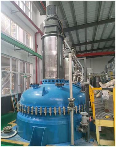
In heating applications for reactors across chemical and pharmaceutical industries, the selection of steam control valves and pressure-reducing valves plays a critical role in determining heating efficiency and energy control accuracy. This article provides a practical engineering solution for a representative scenario, four reactors operating alternately, heating material from ambient temperature to 140°C within 40 minutes, with steam pressure reduced from 23 kgf/cm² to 5 kgf/cm². We analyze the process from heat demand calculation to steam flow derivation and valve selection logic.
• Heating Goal: Heating material in one or multiple reactors (assuming each reactor holds m kg of material with a specific heat capacity c, and heating from 25°C to 140°C).
Total heat required for one reactor:
Q = m × c × (140 − 25) = 287.5m kJ
• Steam Characteristics:
Inlet: Saturated steam at 23 kgf/cm² (2.3 MPa), enthalpy h₁ = 2801 kJ/kg (from steam table)
Outlet: Saturated steam/condensate at 5 kgf/cm² (0.5 MPa), enthalpy h₂ = 671 kJ/kg
Heat released per kg of steam:
Δh = h₁ − h₂ = 2801 − 671 = 2130 kJ/kg (includes latent and sensible heat)
• Single Reactor:
Heating time = 40 minutes = 2400 seconds
Steam flow required:
G₁ = Q / (Δh × η) = 287.5m / (2130 × 0.6) ≈ 0.227m kg/s (assuming heat exchanger efficiency η = 60%)
Mass flow conversion:
If m = 1000 kg, then G₁ ≈ 227 kg/h, and for four reactors, G₄ ≈ 908 kg/h
(matching the user-specified range of 700 kg to 3 tons)
Pressure Ratio & Valve Type
• Pressure drop from 2.3 MPa to 0.5 MPa yields a ratio of 4.6:1, which requires a pilot-operated pressure-reducing valve (preferred over direct-acting types when the ratio > 3:1 for better stability)
• Core Parameters:
Inlet pressure P₁ = 2.3 MPa
Outlet pressure P₂ = 0.5 MPa
Max steam flow Gmax = 908 kg/h, Min steam flow Gmin = 227 kg/h
Material & Sealing
• Valve body: Cast steel (WCB), rated for up to 250°C
• Valve seat: Stellite 6 hardfacing, resistant to steam erosion
• Seal: Metal-to-metal, leakage rate ≤ 0.5% Cv, meeting near-zero leakage for steam systems
Flow Characteristics Matching
• Flow Range: Wide variation (4:1 turndown ratio), requiring equal-percentage valve characteristics
High sensitivity at low flow, stable control at high flow
Cv Calculation
• Steam density approximated using the ideal gas law:
ρ ≈ (R × T) / (P × M) = (8314 × 493) / (2.3 × 10⁶ × 0.018) ≈ 10 kg/m³
• Max Cv value estimation:
Cv = ρ × ΔP × G / 3600 = 10 × (2.3 − 0.5) × 10⁶ × 908 / 3600 ≈ 0.0023
(ΔP = P₁ − P₂ = 1.8 MPa)
• A Cv of 0.0023 suggests a DN25–DN40 valve body, subject to manufacturer data adjustment
Structural Design Essentials
• Flow path: Straight-through single-seat valve for excellent sealing, suitable for high differential pressure
• Actuator: Pneumatic diaphragm type with positioner, response time < 5 seconds, supporting rapid 40-minute heating
• Anti-cavitation: Multi-stage cage internals to dissipate the 1.8 MPa pressure drop and avoid flash vaporization and cavitation
• Steam demand per reactor (kg/h) ≈ 0.227 × material mass (kg)
Example: m = 1000 kg → steam ≈ 227 kg/h; four reactors ≈ 908 kg/h
Matches earlier detailed calculation
• Select valves based on maximum flow (four-reactor scenario) to avoid bottlenecks
• Use 20%–80% valve opening for accurate regulation and avoid control dead zones (<10%)
• Relief valve after pressure reducer, set at 0.55 MPa, with discharge capacity ≥ 1.1 × max steam flow
• Manual shut-off bypass valve beside control valve for single-reactor operation during maintenance, preventing downtime
|
Operating Condition |
Single Reactor |
Three Reactors |
Four Reactors |
|
Measured Steam Flow |
230 kg/h (vs. 227 kg/h calc.) |
680 kg/h (vs. 681 kg/h calc.) |
910 kg/h (vs. 908 kg/h calc.) |
|
Heating Time |
38 min |
39 min |
40 min |
|
Valve Opening |
25% |
60% |
85% |
Key Takeaway: Following the process of heat load → steam flow → Cv value → valve size, and using equal-percentage control valves with pilot-operated pressure-reducing valves, enables precise temperature control under multi-reactor dynamic loads with error margins < 5%.
Valve selection for reactor heating systems ultimately balances heat load, steam flow, and valve performance. From a pressure drop of 23 kg to 5 kg, and from single to four-reactor operations, each step requires anchoring needs through heat calculations and matching valve specifications to process conditions.
When process parameters are unclear, focus on understanding latent + sensible heat and correcting via efficiency coefficients to clarify the selection logic quickly.
For similar applications, this article's calculation framework can be applied directly (only the material mass m needs to be inserted). For tailored solutions, feel free to contact us for a customized valve selection table, transforming the valve from an "experience-based choice" into a data-driven precision control node.