Diaphragm Couplings: Basics You Should Know
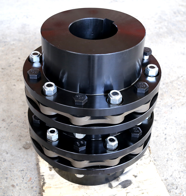
A coupling is a mechanical component used to connect two shafts in different machines or mechanisms so that they can rotate together and transmit torque. In many power transmission systems, the coupling does more than simply transfer rotational power. Depending on its design, it can also compensate for shaft misalignment, reduce vibration, absorb certain dynamic loads, and improve the overall operating characteristics of the shaft system.
A diaphragm coupling is a type of flexible metallic coupling. Instead of using elastomeric elements, gears, or sliding components, it uses thin metallic diaphragms as flexible elements to transmit torque between connected shafts.
This structural principle gives diaphragm couplings several important advantages. They can transmit substantial torque, accommodate certain axial, radial, and angular misalignments, and operate without lubrication. Because the flexible diaphragm deforms elastically instead of relying on relative sliding movement between components, there is little conventional wear during normal operation.
Diaphragm couplings are therefore particularly valuable in high-speed and high-power machinery where reliability, low maintenance, precise torque transmission, and stable dynamic performance are important.
The diaphragm is the central flexible element of the coupling.
It is generally manufactured from high-strength metallic materials capable of undergoing repeated elastic deformation. During operation, the diaphragm transfers torque while simultaneously flexing to accommodate shaft misalignment.
Unlike a rigid coupling, a diaphragm coupling does not require the connected shafts to remain perfectly aligned under all operating conditions. Instead, the diaphragm provides controlled flexibility within its designed limits.
The diaphragm must therefore balance two seemingly opposite requirements: it must be sufficiently strong and stiff to transmit torque while also being flexible enough to compensate for misalignment.
A basic diaphragm coupling contains at least one diaphragm and two hubs or shaft sleeves.
The hubs connect the coupling to the driving and driven shafts. The diaphragm is typically secured to the hubs using bolts, pins, or other fastening arrangements.
The connection must be sufficiently secure to ensure that torque is transmitted reliably without unwanted relative movement.
Proper fastening is especially important because the diaphragm is subjected to repeated cyclic deformation during operation. Any looseness between the diaphragm and hub can increase stress concentration, vibration, and wear around the connection points.
Some diaphragm coupling designs use two or more diaphragm packs.
In these configurations, one or more rigid intermediate elements are positioned between diaphragm sets, with the diaphragm packs connected to hubs on both sides.
The intermediate structure can improve the coupling's ability to accommodate different types of shaft misalignment.
The specific configuration depends on the required torque, shaft spacing, operating speed, and allowable misalignment.
A single diaphragm coupling uses one flexible diaphragm assembly to accommodate shaft misalignment.
Because the diaphragm must deform in a relatively complex manner, its ability to simultaneously handle certain combinations of misalignment may be more limited.
In particular, single diaphragm designs are generally less suitable when significant offset or parallel misalignment must be compensated.
This does not mean single diaphragm couplings are unsuitable for industrial applications. They can be effective when the shaft arrangement is relatively simple and the required misalignment compensation remains within the coupling's specified limits.
A double diaphragm coupling incorporates two flexible diaphragm assemblies separated by an intermediate component.
The two diaphragm sets can flex in different directions, allowing the coupling to accommodate parallel offset more effectively.
This configuration provides greater flexibility when the connected shafts experience multiple forms of misalignment.
The double diaphragm design is therefore often preferred when the shaft system requires more comprehensive misalignment compensation.
The difference between single and double diaphragm designs is not simply the number of diaphragms.
The arrangement of the flexible elements determines how the coupling responds to axial, radial, and angular displacement.
Therefore, engineers should select the configuration based on actual shaft alignment conditions rather than assuming that a double diaphragm coupling is automatically better for every application.
The key operating principle of a diaphragm coupling is elastic deformation.
When torque is applied to the driving shaft, the hub transmits the rotational force to the diaphragm. The diaphragm then transfers the torque to the intermediate component or driven hub.
At the same time, if the shafts are slightly misaligned, the diaphragm bends or flexes to accommodate the displacement.
This allows the coupling to transmit torque while maintaining a degree of flexibility.
A major advantage of diaphragm couplings is that their flexible action is based on elastic deformation rather than sliding friction.
Because the diaphragm and associated components do not normally require continuous sliding movement against one another, there is no conventional friction wear mechanism comparable to some other coupling types.
This contributes to long service life and reduced maintenance requirements.
Diaphragm couplings can transmit rotational speed and torque with high precision.
There is no intentional slip during normal operation, so the driven shaft follows the driving shaft accurately.
This makes diaphragm couplings suitable for applications where maintaining precise rotational synchronization is important.
One of the most important features of a diaphragm coupling is its ability to compensate for shaft misalignment.
Shafts may experience several types of displacement, including axial, radial, and angular misalignment.
A flexible coupling must accommodate these movements without generating excessive reaction forces or damaging the connected equipment.
Diaphragm couplings can provide significant flexibility while maintaining reliable torque transmission.
Axial displacement occurs when two shafts move toward or away from each other along their rotational axis.
Thermal expansion is a common source of axial movement in industrial machinery.
When equipment operates at high temperatures, shafts and connected components can expand. A diaphragm coupling with appropriate axial flexibility can accommodate this movement within its rated limits.
Radial or parallel misalignment occurs when two shaft centerlines are offset from each other.
Excessive radial misalignment can create additional loads on bearings and other machinery components.
A diaphragm coupling can flex to accommodate a certain amount of radial displacement, reducing the mechanical consequences of unavoidable alignment changes.
Angular misalignment occurs when two shaft centerlines intersect at an angle instead of remaining perfectly collinear.
The diaphragm bends to accommodate this angular displacement.
The allowable angular misalignment depends on the coupling design and must remain within the manufacturer's specifications.
Because diaphragm couplings do not depend on continuously sliding components, they can operate with low mechanical noise under normal conditions.
This can be valuable in high-speed rotating machinery where excessive noise may indicate friction, imbalance, or mechanical instability.
A properly selected and installed diaphragm coupling can contribute to smooth machine operation.
A diaphragm coupling can accommodate shaft misalignment and certain dynamic movements, helping reduce the transmission of undesirable mechanical forces.
However, it should not be considered a replacement for proper shaft alignment and balancing.
The coupling works best when the entire rotating system is correctly designed, aligned, and dynamically balanced.
The coupling is part of a larger rotating system that may include motors, pumps, compressors, gearboxes, turbines, and generators.
Changes in coupling stiffness can influence torsional vibration and critical-speed behavior.
Therefore, coupling selection should sometimes include a dynamic analysis of the complete shaft train.
Diaphragm couplings can achieve very high transmission efficiency, with properly designed systems potentially reaching approximately 99.86% under suitable conditions.
High efficiency means that only a small portion of the transmitted energy is lost within the coupling.
This is particularly valuable in high-power machinery because even a small percentage of energy loss can represent substantial power and heat.
Diaphragm couplings are well suited to high-speed rotating equipment.
Because the design can be relatively compact and lightweight and can be dynamically balanced, diaphragm couplings are frequently considered for high-speed shaft systems.
For high-speed applications, however, coupling balance quality is critical. Even a small imbalance can generate substantial centrifugal forces as rotational speed increases.
Diaphragm coupling technology can be adapted for large power transmission systems.
Advanced designs have been manufactured for extremely high power and rotational speed requirements. The actual achievable power, speed, length, and dimensions depend heavily on the coupling design, material, manufacturing process, balancing requirements, and application.
For large power systems, engineers should conduct a complete torsional and dynamic assessment before final selection.
Diaphragm couplings can be designed for demanding temperature environments.
Compared with couplings that rely heavily on polymeric or elastomeric flexible elements, metallic diaphragm couplings are generally less sensitive to certain high-temperature limitations.
Depending on the specific materials and design, diaphragm couplings can be used across a broad temperature range.
The stated operating range must always be verified against the manufacturer's specifications for the specific coupling model.
Diaphragm couplings can also be used in environments involving vibration, shock, and demanding operating conditions.
Applications may include petroleum equipment, chemical machinery, power generation systems, and heavy industrial machinery.
However, environmental factors such as corrosive chemicals, humidity, dust, and extreme temperature should be considered when selecting diaphragm materials and protective measures.
One of the most convenient features of diaphragm couplings is that they generally do not require routine lubrication.
This can significantly reduce maintenance requirements compared with coupling types that depend on lubricated gears or sliding surfaces.
Eliminating routine lubrication also reduces the possibility of lubricant leakage or contamination around the rotating equipment.
The diaphragm operates through elastic deformation rather than continuous sliding.
As a result, the coupling does not normally experience the same type of friction wear associated with many mechanical transmission components.
Nevertheless, fatigue is an important consideration because the diaphragm experiences repeated cyclic deformation.
Regular inspection remains necessary, especially in critical high-speed machinery.
Many diaphragm coupling configurations are designed for relatively convenient installation and removal.
Certain spacer-type configurations can allow coupling maintenance without moving the connected machines, depending on the specific design.
This can reduce maintenance time and simplify service procedures.
Diaphragm couplings are widely used with industrial pumps, especially large power pumps and chemical process pumps.
Pump systems often require reliable torque transmission while accommodating thermal movement and small shaft alignment changes.
A properly selected diaphragm coupling can support these requirements while minimizing maintenance.
Industrial fans and blowers often operate at relatively high rotational speeds.
The coupling must maintain stable power transmission while limiting excessive vibration.
Diaphragm couplings can be suitable for such systems when correctly sized and balanced.
Compressors are particularly demanding because they may operate continuously at high speed and high power.
Coupling failure can cause significant production downtime.
Diaphragm couplings can provide accurate torque transmission, high efficiency, and misalignment compensation for suitable compressor trains.
Power generation equipment represents another major application area.
Steam turbines, gas turbines, and generators may require high-speed couplings capable of transmitting substantial power.
The coupling's torsional stiffness, critical-speed behavior, balance quality, and misalignment capability must all be evaluated carefully.
Petroleum and chemical processing machinery often operates continuously under demanding conditions.
Diaphragm couplings can be used in pumps, compressors, fans, and other rotating equipment in these industries.
Their lack of routine lubrication can also be beneficial where maintenance access is limited.
High-speed propulsion and power transmission systems in ships and aircraft require lightweight and reliable mechanical components.
Diaphragm couplings can be used in selected marine and aerospace applications where high-speed operation, low weight, precise torque transmission, and misalignment compensation are required.
One possible cause of abnormal noise is excessive spacing between the two coupling halves.
If the distance is too large, the diaphragm may experience excessive axial forces.
These forces can increase stress around the bolt holes or connection areas and eventually cause wear or abnormal movement.
This may result in vibration and unusual operating noise.
The correct axial spacing should therefore be confirmed during installation.
Excessive axial displacement can cause the diaphragm to operate outside its intended deformation range.
The resulting additional stress may produce vibration, abnormal noise, or premature fatigue.
The coupling should be checked whenever the connected machines experience unexpected axial movement.
Angular misalignment beyond the rated limit can also cause abnormal behavior.
If the shaft centerlines are not properly aligned, the diaphragm must flex excessively during rotation.
This can increase reaction forces and cyclic stress.
Proper alignment is therefore one of the most important factors in preventing diaphragm coupling problems.
The driving and driven machines should normally operate according to the required speed relationship.
If the two sides experience an abnormal speed difference, the coupling may be subjected to unexpected torsional conditions.
This can result in vibration and noise.
The cause should be investigated rather than assuming that the coupling itself is defective.
In motor-driven systems, a faulty speed encoder or speed sensor can cause unstable motor speed.
If the motor speed continuously fluctuates, the diaphragm coupling may experience changing torsional conditions.
This can appear as abnormal vibration or noise.
Therefore, when a coupling develops unusual noise, the motor control and speed feedback system should also be checked.
The first step should be to verify the alignment of the connected shafts.
Both angular and parallel alignment should be checked using appropriate precision alignment equipment.
Visual inspection alone may not be sufficient for high-speed machinery.
The axial distance between coupling halves should be measured and compared with the manufacturer's specified installation dimension.
Incorrect spacing can change the diaphragm's operating condition and lead to excessive stress.
Bolts, pins, and other fastening components should be inspected for looseness, deformation, or wear.
Loose fasteners can create small amounts of relative movement that become increasingly significant at high rotational speed.
The diaphragm should be inspected for cracks, deformation, corrosion, scratches, or other signs of fatigue.
Because the diaphragm is a critical load-bearing flexible element, even small defects should be evaluated carefully.
If the mechanical components appear normal, the motor, speed sensor, encoder, drive, and control system should be checked.
Unstable motor speed can create torsional fluctuations that manifest as coupling vibration or noise.
Proper alignment is essential for diaphragm coupling reliability.
The coupling is designed to compensate for limited misalignment, not to correct poor installation.
Excessive misalignment will increase diaphragm deformation and fatigue.
Fasteners should be tightened according to the manufacturer's recommended torque values.
Under-tightening can allow movement, while excessive tightening may damage components or create inappropriate stress concentrations.
The coupling should be installed at the specified axial position.
The distance between the coupling halves or diaphragm packs must remain within the recommended range.
High-speed coupling systems should be dynamically balanced as required.
Balancing becomes increasingly important as rotational speed increases because centrifugal forces rise rapidly with speed.
An appropriately balanced coupling can help reduce vibration and improve shaft system stability.
The coupling must be capable of transmitting the required torque continuously and under transient conditions.
Engineers should consider not only rated motor power but also startup torque, acceleration, shock loads, and potential overloads.
Rotational speed is another critical parameter.
A coupling suitable for a low-speed machine may not be appropriate for a high-speed compressor or turbine.
The coupling's maximum permitted speed and balance quality must be verified.
The expected axial, radial, and angular misalignment should be determined.
The selected coupling should have sufficient capacity to accommodate these movements without exceeding its rated limits.
Torsional stiffness affects the dynamic response of the shaft system.
Changing the diaphragm geometry, intermediate shaft dimensions, outer diameter, or wall thickness can influence torsional characteristics and critical speeds.
For high-performance systems, the coupling should be selected as part of a complete torsional analysis rather than as an isolated component.
A diaphragm coupling is a sophisticated form of metallic flexible coupling designed to transmit torque while accommodating controlled shaft misalignment.
Its main advantages include high torque capacity, strong misalignment compensation, low maintenance, high transmission efficiency, precise speed transmission, low noise, and suitability for high-speed and high-power applications.
The diaphragm acts as the key flexible element, using elastic deformation rather than sliding movement to accommodate axial, radial, and angular displacement.
Although diaphragm couplings offer excellent performance, they still require correct selection, installation, alignment, and maintenance.
Abnormal noise may result from excessive spacing, excessive axial or angular misalignment, speed differences, loose fasteners, diaphragm damage, or motor control problems.
Therefore, troubleshooting should examine the entire rotating system rather than focusing only on the coupling.
With proper engineering, installation, balancing, and inspection, diaphragm couplings can provide highly reliable torque transmission for pumps, fans, compressors, turbines, generators, chemical machinery, petroleum equipment, marine systems, aerospace equipment, and other demanding applications.
For high-speed and high-power machinery, the coupling should be regarded as an important part of the complete shaft system. Selecting the correct diaphragm configuration, material, dimensions, torsional stiffness, and misalignment capacity can help improve operating stability, reduce maintenance requirements, and extend the service life of the entire mechanical transmission system.
