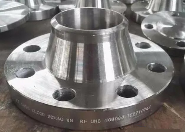
Neck flanges are widely used in industrial piping systems where reliable mechanical connections, pressure resistance, and long-term sealing performance are important. Compared with simpler flange designs, a neck flange incorporates a raised neck that provides additional structural support and helps distribute stresses between the flange and the connected pipe.
The neck geometry is one of the most important characteristics of this flange type. Instead of abruptly transferring loads from the pipe to the flange plate, the tapered transition allows forces and bending moments to be distributed more gradually.
This structural advantage makes neck flanges particularly useful in demanding applications involving pressure, temperature changes, vibration, and repeated mechanical loading.
Welding is a critical part of the installation process. A properly designed and executed weld creates a continuous connection between the pipe and flange, allowing the assembled piping system to withstand internal pressure and external loads.
For this reason, selecting the correct welding method and controlling the welding process are essential for flange reliability.
A weld neck flange consists mainly of a flange plate and an extended neck.
The neck normally has a tapered profile that transitions from the flange body toward the pipe. The pipe is aligned with the flange bore, and the neck is welded to the pipe using a butt-welding configuration.
This design differs significantly from a slip-on flange, where the pipe is inserted into the flange and welded around the connection.
The weld neck configuration creates a more continuous load path between the pipe and flange.
The neck helps reduce stress concentration at the flange-to-pipe connection.
When a piping system operates under pressure, the flange can experience several types of loading. These may include internal pressure, bending moments, thermal expansion, vibration, and external forces from connected equipment.
A properly designed neck helps transfer these loads into the pipe more smoothly.
This is one reason weld neck flanges are commonly selected for high-pressure and high-temperature applications.
The extended neck increases the effective structural stiffness of the flange connection.
Greater rigidity can help limit deformation when the piping system is subjected to pressure or external loads.
This is particularly important for large-diameter or high-pressure systems.
A major advantage of the weld neck configuration is its ability to reduce abrupt stress transitions.
A flange without an appropriate transition may experience relatively high localized stress near the connection.
The tapered neck provides a smoother geometry and allows mechanical loads to be transferred more gradually.
Industrial piping systems can experience repeated temperature changes.
When the temperature changes, the pipe expands and contracts.
If the pipe and flange experience different deformation rates or if the system is restrained, thermal stresses can develop around the connection.
The weld neck configuration can provide a more robust connection for such applications when properly engineered.
Weld neck flanges are generally connected to pipes through butt welding.
The pipe and flange neck are aligned so that their prepared ends can be joined by a full-penetration weld.
The exact joint preparation depends on pipe and flange dimensions, material grade, wall thickness, welding procedure, and applicable standards.
For demanding pressure applications, achieving appropriate weld penetration is critical.
Incomplete penetration can create a discontinuity in the load path and may become a potential location for fatigue or cracking.
The welding procedure should therefore be qualified for the material and thickness involved.
Before welding begins, the pipe and flange must be properly aligned.
Misalignment can create additional stress in the completed joint and may also make bolt-hole alignment difficult during later installation.
The flange face should remain correctly oriented throughout welding.
Before welding, the joint surfaces should be clean and free from oil, grease, moisture, rust, paint, and other contaminants that could negatively affect weld quality.
Cleaning is particularly important when welding stainless steels, alloy steels, or other materials that may be sensitive to contamination.
The flange should be inspected before welding to confirm:
- Nominal size.
- Pressure class.
- Bore diameter.
- Neck dimensions.
- Flange thickness.
- Bolt-hole arrangement.
- Facing type.
- Material grade.
The pipe dimensions should also be verified.
Incorrect dimensions can create fit-up problems or lead to the use of incompatible components.
The pipe and flange neck may require a specific bevel configuration before welding.
The bevel angle, root face, root gap, and other joint preparation dimensions should follow the approved welding procedure.
Improper preparation can lead to lack of fusion, incomplete penetration, excessive reinforcement, or other weld defects.
A qualified Welding Procedure Specification, or WPS, should define the essential welding parameters.
Depending on the application, the WPS may specify:
- Base metal.
- Filler metal.
- Welding process.
- Preheating temperature.
- Interpass temperature.
- Current.
- Voltage.
- Travel speed.
- Welding position.
- Number of passes.
- Post-weld heat treatment.
Following the qualified procedure helps maintain consistent weld quality.
The welding operator should have appropriate qualifications for the welding process, material, position, and joint configuration.
A qualified procedure alone does not guarantee weld quality if the welding operation is not performed correctly.
Experienced welders are particularly important for critical piping systems where dimensional accuracy and weld integrity are essential.
Some carbon steels and alloy steels may require preheating before welding.
Preheating can reduce the cooling rate of the weld area and help reduce the risk of undesirable microstructures or hydrogen-related cracking.
The required temperature depends on material chemistry, thickness, restraint, hydrogen control, and the qualified welding procedure.
The interpass temperature should also be controlled.
Excessive temperature between passes can affect metallurgical properties, while insufficient temperature may reduce the effectiveness of the intended welding procedure.
The WPS should specify appropriate limits.
Stainless steel flange welding requires additional attention to heat input and contamination.
Excessive heat may affect corrosion resistance or produce undesirable metallurgical conditions depending on the grade.
The welding procedure should therefore be developed specifically for the stainless steel grade being used.
Shielded Metal Arc Welding, commonly known as SMAW, is widely used in industrial field applications.
It is relatively flexible and does not require a shielding gas supply.
However, electrode selection, storage, moisture control, and slag removal are important for weld quality.
Gas Tungsten Arc Welding, or GTAW/TIG, provides excellent control of the welding arc and is often used for root passes where high-quality penetration is required.
It can be especially useful for stainless steel and alloy materials.
The process is generally slower than some alternatives, but it can provide excellent weld control.
Gas Metal Arc Welding, or GMAW/MIG, can offer relatively high productivity.
It may be suitable for certain shop fabrication environments where controlled conditions are available.
Shielding gas selection and flow control are important to avoid porosity and contamination.
Flux-Cored Arc Welding can provide high deposition rates and may be useful for certain carbon steel and alloy steel fabrication applications.
The exact suitability depends on the material, welding position, code requirements, and qualified welding procedure.
Welding involves localized heating and cooling.
As the weld metal and adjacent base metal expand and contract, residual stresses and distortion can develop.
Flanges are particularly sensitive because their dimensional accuracy is important for subsequent bolting and sealing.
Correct fit-up is the first step in controlling distortion.
The pipe should be centered correctly within the flange neck, and the flange face should be maintained in the required orientation.
Appropriate welding sequences can help minimize distortion.
For larger components, welders may use controlled sequencing to distribute heat more evenly around the circumference.
The specific sequence should be established according to the approved welding procedure.
Tack welds help maintain alignment before final welding.
They should be properly positioned and sufficiently strong to prevent movement during welding.
Defective tack welds should not simply be incorporated into the final weld without proper evaluation.
Visual inspection is an important first step after welding.
Inspectors may check for:
- Surface cracks.
- Undercut.
- Excessive reinforcement.
- Incomplete weld profile.
- Surface porosity.
- Arc strikes.
- Spatter.
- Distortion.
- Incorrect flange orientation.
Visual inspection cannot identify every internal defect, but it can identify many surface problems.
Radiographic testing can be used to detect certain internal weld discontinuities.
It is often applied to critical butt welds when required by the applicable code or project specification.
Ultrasonic testing can provide information about internal discontinuities and weld integrity.
It can be especially useful for thicker sections or applications where volumetric inspection is required.
Dye penetrant testing can identify surface-breaking defects in suitable non-porous materials.
It is often useful for detecting surface cracks that may not be visible during ordinary visual inspection.
Magnetic particle testing can detect surface and near-surface discontinuities in ferromagnetic materials.
The inspection method should be selected according to the base material and applicable inspection requirements.
A weld neck flange uses a tapered neck and butt-weld connection.
A slip-on flange is installed over the outside of the pipe and generally uses fillet welds on the inside and outside.
The structural geometry and weld arrangement are therefore different.
Slip-on flanges may have lower initial purchase costs and can be relatively convenient to install.
However, the welding workload and inspection requirements must also be considered when evaluating the overall installation cost.
Weld neck flanges generally require more careful preparation and welding, but their structural performance makes them attractive for demanding service.
For high-pressure, high-temperature, or severe cyclic applications, weld neck flanges are often preferred because of their favorable stress distribution.
The final selection should always be based on the applicable design code, pressure class, material, temperature, and service conditions.
Threaded flanges connect to pipes using matching threads.
One advantage is that they can be installed without welding.
This can be useful in selected low-risk applications where welding is undesirable or impractical.
However, threaded connections may not be appropriate for every pressure, temperature, or cyclic service.
Slip-on flanges fit over the pipe and are normally welded on the inside and outside.
Their relatively simple installation and lower initial component cost make them common in general piping applications.
However, they may require more welding work than some alternatives.
Lap joint flanges are commonly used together with lap joint stub ends.
The flange itself does not need to be permanently welded to the pipe in the same way as a weld neck flange.
This arrangement can be useful where frequent dismantling or special material combinations are required.
Socket weld flanges contain a socket into which the pipe is inserted.
The pipe is generally welded around the outside of the connection.
The internal configuration can provide a relatively clean flow path when properly designed and installed.
Socket weld flanges are often used for smaller-diameter piping systems, depending on the application and applicable standards.
Lack of penetration occurs when the weld does not extend adequately through the joint.
Potential causes include incorrect root gap, insufficient heat input, improper joint preparation, or unsuitable welding technique.
This problem can reduce joint integrity and must be prevented through appropriate procedure qualification and inspection.
Lack of fusion occurs when the weld metal does not properly fuse with the base material or previous weld layer.
It may result from insufficient heat, incorrect electrode angle, excessive travel speed, or contamination.
Porosity consists of gas pockets trapped within the weld metal.
Moisture, contamination, poor shielding, or incorrect welding parameters may contribute to porosity.
Cracking is one of the most serious weld defects.
Potential causes include unsuitable material conditions, excessive restraint, hydrogen, thermal stresses, improper heat treatment, or inappropriate welding procedures.
Any suspected crack should be evaluated by qualified personnel.
Welding consumables should be stored and handled according to the manufacturer's requirements.
Moisture-sensitive electrodes may require controlled storage and rebaking procedures.
Incorrect consumable handling can increase the risk of hydrogen-related problems and other weld defects.
Heat input should remain within the qualified range.
Excessive heat can affect material properties and increase distortion, while insufficient heat may result in poor fusion.
Both the base metal and filler materials should be kept clean.
Oil, moisture, paint, rust, and other contaminants should be removed from the welding area.
Certain materials and applications may require post-weld heat treatment.
The purpose can include reducing residual stresses and achieving specified metallurgical properties.
Whether PWHT is required depends on material, thickness, service conditions, and applicable code requirements.
After welding and any required heat treatment, the flange should undergo final inspection.
The inspection should verify both weld quality and flange geometry.
The flange face should be protected from damage during handling and storage.
The sealing surface of the flange should be protected during transportation, fabrication, and installation.
Damage, scratches, dents, or corrosion on the sealing face can compromise gasket performance.
A gasket should be selected according to pressure, temperature, fluid compatibility, flange facing, and applicable design requirements.
The gasket is an important part of the overall sealing system.
Bolts should be tightened using an appropriate sequence and torque or tension procedure.
Uneven tightening can cause gasket compression problems or flange deformation.
For critical services, controlled bolt tensioning may be appropriate.
Weld neck flanges are widely used in oil and gas piping systems.
These systems may involve high pressure, temperature variation, vibration, and demanding operating conditions.
The structural characteristics of weld neck flanges make them suitable for many such applications.
Chemical plants often handle corrosive, toxic, or hazardous fluids.
Reliable flange connections are essential for preventing leakage and maintaining process safety.
Material selection must consider chemical compatibility in addition to mechanical properties.
Power plants use piping systems operating under demanding pressure and temperature conditions.
Steam, feedwater, cooling water, and other process systems may require carefully selected flanges and welded joints.
Petrochemical equipment often involves continuous operation and significant thermal and mechanical loads.
Weld neck flanges can provide a robust connection for suitable high-performance piping systems.
The flange pressure rating should be suitable for the system's design pressure and temperature.
The pressure class should never be selected based solely on normal operating pressure.
Temperature affects both material properties and allowable pressure ratings.
The selected flange must be compatible with the full operating temperature range.
The flange material should be compatible with the pipe and service fluid.
For corrosive services, stainless steel or other corrosion-resistant alloys may be necessary.
The flange and pipe materials should be suitable for the selected welding process.
Material chemistry, thickness, preheating, filler metal, and heat treatment requirements should all be evaluated before welding begins.
Neck flanges provide an important combination of structural strength, stress distribution, and reliable pipe connection.
Their extended neck helps transfer loads between the pipe and flange more smoothly and can make them particularly suitable for high-pressure, high-temperature, and cyclic service.
However, the advantages of a weld neck flange can only be fully realized when the welding process is properly controlled.
Joint preparation, alignment, welding procedure qualification, material selection, heat control, consumable management, inspection, and post-weld treatment all contribute to final connection quality.
A weld neck flange is not automatically the best choice for every piping system.
Threaded, slip-on, lap joint, and socket weld flanges may be more appropriate depending on pipe size, pressure, temperature, material, installation conditions, maintenance requirements, and applicable standards.
The correct flange should therefore be selected based on the actual operating conditions rather than initial purchase price alone.
Successful flange welding requires a systematic approach.
From material verification and joint preparation to welding, inspection, installation, and maintenance, every stage can influence the final performance of the piping connection.
For critical industrial systems, welding should be performed according to qualified procedures by competent personnel, with inspection and testing appropriate to the applicable codes and project specifications.
When these principles are followed, weld neck flanges can provide strong, durable, and dependable connections for demanding piping systems across oil and gas, chemical processing, power generation, petrochemical, and other industrial applications.
