Pilot Structure Optimization of Pilot-Operated Safety Valves for Severe Service Conditions
Abstract: The main valve disc is a critical component of a pilot-operated safety valve, directly affecting its sealing performance and opening, discharge, and closing functions. Smooth reciprocating motion of the disc within the guide sleeve is essential for reliable valve operation. To address disc jamming, a common problem under high-pressure conditions or when handling media containing impurities, this study proposes improvements to the conventional pilot structure. The design modifications are intended to ensure smoother disc movement during installation and operation, improving the valve's adaptability to harsh service conditions in industries such as coal chemical processing and petrochemicals. The proposed improvements provide a practical approach to enhancing sealing reliability in high-parameter process equipment and offer valuable guidance for engineering applications.
Safety valves play a vital role in protecting pressure-containing equipment, including boilers, pressure vessels, and pipelines, from overpressure damage. As critical pressure-relief devices and the last line of defense for production systems, they help maintain safe equipment operation and protect personnel. As industrial processes continue to evolve, the performance requirements for safety valves have become increasingly demanding. Under severe service conditions involving high pressures, large diameters, and complex media, valve reliability is particularly important to the safety and stability of industrial operations.
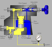
Pilot-operated safety valves consist of a main valve and a pilot valve and are widely used in industrial pressure-relief systems. The pilot valve operates on the direct-acting principle and controls the main valve by regulating the discharge of the working medium. This configuration allows the working medium to exert a much greater opening force on the main valve disc than is typically available in direct-acting safety valves. In addition, pilot-operated safety valves are less susceptible to fluctuations in back pressure, making them particularly suitable for high-pressure and large-diameter applications. As a result, they have become widely used in many industrial sectors.
In practical applications, the main valve disc of a conventional pilot-operated safety valve can become stuck under high-pressure conditions or when handling media containing impurities. This can result in several problems, including leakage, failure to open or reseat properly, and performance parameters exceeding specified limits, thereby posing safety risks to production operations. For example, a pilot-operated safety valve in a coal-to-chemical plant failed to reseat after opening because its main valve disc became stuck. The failure was attributed to the high set pressure and the substantial particulate content of the process medium. To address this problem, this study investigates the causes of main valve disc jamming in practical applications and proposes modifications to the pilot structure. The improvements are intended to enhance valve reliability and operational safety under complex service conditions, meet the increasingly stringent performance requirements of modern industrial processes, and support safe and stable plant operation.
The conventional main valve disc in a pilot-operated safety valve uses a metal-to-metal guiding mechanism, in which two annular surfaces guide the disc within the guide sleeve through a clearance fit. Two O-rings are installed on these guiding surfaces to provide sealing, as shown in Figure 1. This design offers high reliability when handling clean media. The O-rings also provide effective sealing between the disc and the guide sleeve, preventing medium leakage and ensuring proper valve operation.
Figure 1. Schematic of the conventional main valve disc structure
Although the conventional guiding structure performs well with clean media, its metal-to-metal clearance fit requires precise dimensional tolerances and can cause localized friction. Under high-pressure conditions or when handling media containing significant impurities, friction between the valve disc and guide sleeve can increase substantially. If impurities enter the clearance, the components may seize, preventing the valve from opening or reseating and creating serious safety hazards. Such failures can disrupt valve operation, cause equipment overpressure, and threaten the safety of the entire production system, potentially resulting in significant economic losses. Consequently, conventional pilot-operated safety valves with this guiding structure are generally unsuitable for such demanding service conditions.
To reduce main valve disc seizure and improve reliability and service life under complex operating conditions, the original disc structure was optimized based on studies of other piston-type products and a detailed technical analysis. The improved design is shown in Figure 2. The main modifications are as follows:
- Increased clearance between the disc and guide sleeve. The clearance was enlarged to reduce direct metal-to-metal contact, allowing a certain amount of impurities to enter without causing the disc and guide sleeve to seize. This improves operational reliability when handling media containing impurities.
- Addition of a guide band. The original metal guiding surface was replaced with a guide band whose annular surface protrudes beyond the disc's outer surface after installation, allowing it to contact the inner wall of the guide sleeve and guide the disc during reciprocating motion. Because the guide band is the only component in contact with the sleeve's inner surface, frictional resistance is significantly reduced, further lowering the risk of seizure.
- Removal of the lower O-ring. The improved design retains only the upper O-ring for sealing. Removing the second O-ring reduces friction between the disc and guide sleeve. Experimental tests confirmed that the required sealing performance was maintained, allowing guiding performance to be improved without compromising sealing.
Figure 2. Schematic of the improved main valve disc structure
As part of the guiding structure redesign, the sealing arrangement between the valve disc and guide sleeve was also optimized. The original design used two O-rings positioned at different heights to help keep the disc centered and vertically aligned, reducing the risk of severe jamming caused by tilting. However, detailed analysis and experimental tests showed that removing one O-ring from the improved design did not significantly compromise sealing performance. The guide band provides effective guidance and support, maintaining the disc's alignment during reciprocating motion and ensuring reliable sealing. Removing one O-ring also reduces friction between the O-ring and guide sleeve, lowering resistance to disc movement and improving the safety valve's operational reliability and service life.
Guide strips are widely used in hydraulic cylinders and piston rods that undergo linear reciprocating motion. Their primary functions are to guide and support the piston and piston rod, withstand radial loads, prevent direct metal-to-metal contact between moving components, and reduce wear and friction. Compared with conventional metal guides, nonmetallic guide strips offer several advantages, including lower manufacturing costs, high load-bearing capacity, reduced local stress concentrations, excellent wear resistance, and long service life. The metal-to-plastic contact interface also minimizes mutual wear, provides favorable friction characteristics, and helps absorb and damp mechanical vibrations. In addition, nonmetallic guide strips provide effective wiping action and can capture fine foreign particles. Therefore, incorporating a guide strip into the main valve disc's guiding structure can reduce resistance to disc movement under high-pressure conditions or in media containing impurities, thereby improving the smoothness and reliability of valve operation.
PTFE (polytetrafluoroethylene) is the primary material used for guide bands, and its mechanical properties can be tailored by adding different fillers to meet specific operating requirements. For example, carbon fillers improve self-lubricating properties, carbon fibers enhance wear resistance, and bronze fillers increase load-bearing capacity. In safety valve applications, the main valve disc moves vertically within the guide sleeve, resulting in relatively low radial contact pressure and friction. Therefore, carbon fiber-filled PTFE was selected for the guide band. This material offers good self-lubricating properties and wear resistance, helping maintain smooth disc movement and reliable sealing under high-pressure conditions and in media containing impurities.

The radial load-bearing capacity and elastic deformation of the guide strip are critical design considerations. To ensure that the guide strip provides adequate support for the valve disc and withstands radial loads during operation, the minimum required guide length must first be calculated based on the operating conditions. The width and number of guide strips can then be determined accordingly. The minimum guide length, (L), is calculated using the following equation:
(1)
where (F) is the maximum radial load (N), (f) is the safety factor (typically 2), (P_r) is the maximum allowable bearing pressure of the guide strip (N/mm²), and (d_N) is the piston diameter (mm).
The calculation is illustrated using an 8T10 pilot-operated safety valve with a set pressure of 6 MPa. Figure 3 shows the limiting condition in which the main valve disc tilts to its maximum angle within the guide sleeve, resulting in the maximum radial force acting on the disc. For a conservative and simplified calculation, the pressure in the gas chamber above the disc at the instant of opening is assumed to be zero, and back pressure is neglected. Let the tilt angle be (90° - α). The resulting cross-sectional geometry forms a right-angled triangle with side lengths (a), (b), and (c).
Figure 3. Schematic of the forces acting on the valve disc

The main valve disc is subjected primarily to the force exerted by the working medium, its own weight acting vertically downward, and the spring force. The medium forces acting on opposite sides of the disc cancel each other out. Let the radial force acting on the main valve disc at the moment of opening be Fdiameter; then Fdiameter can be calculated as follows:
where Ps is the set pressure, corresponding to the medium pressure at the instant of opening (MPa); r is the valve disc radius over which the medium pressure acts (mm); and G is the weight of the valve disc (N).
The valve disc height c = 230 mm, and the maximum clearance between the disc and the guide sleeve a ≈ 0.6 mm. Therefore, cos α = a/c = 0.00260869, giving Fdiameter = 435.54 N. Taking the maximum allowable load-bearing capacity of the carbon-filled PTFE guide band as 10 N/mm², we obtain:
L=Fradial×fdN×Pr=435.54×2184.5×10=0.4721 mmL=dN×PrFradial×f=184.5×10435.54×2=0.4721 mm. The minimum guide length is therefore 0.48 mm.
The appropriate guide strip width is selected from Table 1 based on the inner diameter of the safety valve guide sleeve, which corresponds to the cylinder bore diameter listed in the table. The number of guide strips is then determined based on the calculated minimum guide length.
Table 1. Recommended Guide Band Widths
|
Series No. |
Cylinder Bore Diameter (mm) |
Guide Band Width (mm) |
Guide Band Thickness (mm) |
|
GP41 |
8–20 |
2.5 |
1.55 |
|
GP43 |
10–50 |
4.0 |
1.55 |
|
GP65 |
16–140 |
5.6 |
2.5 |
|
GP69 |
60–220 |
9.7 |
2.5 |
|
GP73 |
130–400 |
15.0 |
2.5 |
For the 8T10 safety valve with a set pressure of 6 MPa and a disc diameter of 180 mm, the applicable guide band series are GP69 and GP73, with widths of 9.7 mm and 15 mm, respectively. Both widths exceed the calculated minimum required guide length of 0.48 mm and therefore meet the basic load-bearing requirements. As shown in Table 1, two guide band widths are recommended for the same cylinder bore diameter. Accordingly, experimental tests are conducted to investigate the effects of guide band width and number on guiding performance.
To investigate the effects of guide band width and quantity on guiding performance, tests were conducted using two safety valve specifications, 1.5D2 and 8T10, representing the smallest and largest sizes in the product range. Three test configurations were established for each specification, denoted as “guide band width × quantity.” Two configurations used the guide band widths recommended in Table 1, both of which exceeded the calculated minimum required guide length. A third configuration used two narrower guide bands to improve load-bearing capacity and optimize the coaxiality between the disc and guide sleeve. The test configurations are listed in Table 2.
Table 2. Test Configurations
|
Safety Valve Specification |
Scheme 1 |
Scheme 2 |
Scheme 3 |
|
1.5D2 |
5.6 mm × 1 |
5.6 mm × 2 |
9.7 mm × 1 |
|
8T10 |
9.7 mm × 1 |
9.7 mm × 2 |
15 mm × 1 |
The tests focused on two key aspects: operational performance and sealing integrity. The objective was to determine whether all six test configurations could achieve lift-off and reseating and maintain an effective seal. Each test valve disc underwent 20 operating cycles on the test rig, during which the lift-off and reseat pressures were recorded to evaluate operational stability. Sealing tests were then conducted to assess sealing performance. The test valve disc is shown in Figure 4.
Figure 4. Schematic of the Test Valve Disc
The test results for the 1.5D2 safety valve are presented in Table 3. The results show that the guide band configuration had little effect on lift-off pressure but a more pronounced effect on reseat pressure. Therefore, a line graph was plotted using the reseat pressure data to facilitate comparison among the three test schemes.
Figure 5 shows the variation in reseat pressure during testing of the 1.5D2 safety valve. The reseat pressure fluctuated only slightly, generally remaining between 1.25 and 1.28 MPa. Among the tested configurations, the 5.6 mm-wide guide band configuration exhibited the smallest fluctuations, indicating the best guiding performance. The test results for the 8T10 safety valve are presented in Table 4. Consistent with the results for the 1.5D2 safety valve, the guide band had little effect on lift-off pressure but a more pronounced effect on reseat pressure.
Figure 5. Reseat Pressure Analysis for the 1.5D2 Safety Valve
Table 4. Test Results for the 8T10 Safety Valve
|
Test No. |
9.7 mm × 1 Opening Pressure (MPa) |
9.7 mm × 1 Reseat Pressure (MPa) |
9.7 mm × 2 Opening Pressure (MPa) |
9.7 mm × 2 Reseat Pressure (MPa) |
15 mm × 1 Opening Pressure (MPa) |
15 mm × 1 Reseat Pressure (MPa) |
|
1 |
0.87 |
0.70 |
0.87 |
0.68 |
0.87 |
0.64 |
|
2 |
0.87 |
0.66 |
0.87 |
0.68 |
0.86 |
0.64 |
|
3 |
0.87 |
0.64 |
0.87 |
0.68 |
0.86 |
0.64 |
|
4 |
0.87 |
0.64 |
0.87 |
0.69 |
0.86 |
0.64 |
|
5 |
0.87 |
0.64 |
0.87 |
0.69 |
0.86 |
0.69 |
|
6 |
0.87 |
0.70 |
0.87 |
0.66 |
0.86 |
0.64 |
|
7 |
0.87 |
0.66 |
0.87 |
0.66 |
0.86 |
0.64 |
|
8 |
0.87 |
0.66 |
0.87 |
0.68 |
0.86 |
0.64 |
|
9 |
0.87 |
0.66 |
0.87 |
0.68 |
0.87 |
0.64 |
|
10 |
0.87 |
0.66 |
0.87 |
0.69 |
0.87 |
0.64 |
|
11 |
0.87 |
0.64 |
0.87 |
0.68 |
0.87 |
0.64 |
|
12 |
0.87 |
0.66 |
0.87 |
0.66 |
0.87 |
0.64 |
|
13 |
0.87 |
0.66 |
0.87 |
0.68 |
0.87 |
0.64 |
|
14 |
0.87 |
0.66 |
0.87 |
0.66 |
0.86 |
0.64 |
|
15 |
0.87 |
0.66 |
0.87 |
0.66 |
0.86 |
0.64 |
|
16 |
0.87 |
0.70 |
0.87 |
0.69 |
0.88 |
0.68 |
|
17 |
0.87 |
0.65 |
0.87 |
0.66 |
0.87 |
0.64 |
|
18 |
0.87 |
0.65 |
0.87 |
0.66 |
0.88 |
0.64 |
|
19 |
0.87 |
0.65 |
0.87 |
0.66 |
0.87 |
0.64 |
|
20 |
0.87 |
0.65 |
0.87 |
0.68 |
0.87 |
0.65 |
Figure 6 shows the reseat pressure curves obtained from the 8T10 tests. Reseat pressure fluctuated only slightly across all three test configurations, generally ranging from 0.64 to 0.70 MPa. Among the three configurations, the 9.7 mm × 2 configuration exhibited the smallest fluctuations, indicating the best guiding performance.
Figure 6. Reseat Pressure Analysis for the 8T10 Safety Valve
Comparison of the test results for the two valve specifications shows that using two guide bands provides better guiding performance than using a single band. This improvement is attributed to the increased guiding length provided by the dual-band configuration. Compared with a single guide band, two guide bands reduce the tilting angle of the valve disc within the guide sleeve, thereby reducing radial forces and friction and ensuring smoother reciprocating motion.
Sealing tests were conducted on the 1.5D2 and 8T10 safety valves after every four operational performance tests, resulting in five sealing tests for each valve. The results are presented in Tables 5 and 6, respectively. As a common sealing element, the O-ring relies primarily on elastic deformation to conform closely to the sealing surface under pressure and prevent fluid leakage.
The results show that both safety valve specifications met the “no visible leakage” criterion in all sealing tests conducted at different test pressures, demonstrating consistent and reliable sealing performance. The valves maintained effective sealing after repeated operational cycles, confirming the reliability of the sealing structure under the tested conditions and its suitability for practical engineering applications.
Table 5. Sealing Test Results for the 1.5D2 Safety Valve
|
Test No. |
5.6 mm × 1 Sealing Pressure (MPa) |
Test Result |
5.6 mm × 2 Sealing Pressure (MPa) |
Test Result |
9.7 mm × 1 Sealing Pressure (MPa) |
Test Result |
|
1 |
1.5 |
No visible leakage |
1.5 |
No visible leakage |
1.5 |
No visible leakage |
|
2 |
1.5 |
No visible leakage |
1.5 |
No visible leakage |
1.5 |
No visible leakage |
|
3 |
1.5 |
No visible leakage |
1.5 |
No visible leakage |
1.5 |
No visible leakage |
|
4 |
1.5 |
No visible leakage |
1.5 |
No visible leakage |
1.5 |
No visible leakage |
|
5 |
1.5 |
No visible leakage |
1.5 |
No visible leakage |
1.5 |
No visible leakage |
Table 6. Sealing Test Results for the 8T10 Safety Valve
|
Test No. |
9.7 mm × 1 Sealing Pressure (MPa) |
Test Result |
9.7 mm × 2 Sealing Pressure (MPa) |
Test Result |
15 mm × 1 Sealing Pressure (MPa) |
Test Result |
|
1 |
0.78 |
No visible leakage |
0.78 |
No visible leakage |
0.78 |
No visible leakage |
|
2 |
0.78 |
No visible leakage |
0.78 |
No visible leakage |
0.78 |
No visible leakage |
|
3 |
0.78 |
No visible leakage |
0.78 |
No visible leakage |
0.78 |
No visible leakage |
|
4 |
0.78 |
No visible leakage |
0.78 |
No visible leakage |
0.78 |
No visible leakage |
|
5 |
0.78 |
No visible leakage |
0.78 |
No visible leakage |
0.78 |
No visible leakage |
A coal gasification unit at a coal chemical plant operates under demanding conditions characterized by high pressure and high impurity levels. The improved pilot-operated safety valve developed in this study was therefore installed at critical locations within the unit. Field applications have demonstrated that the improved safety valve maintains stable and reliable operation under these harsh conditions, with no abnormalities observed. Its reliable performance helps ensure the safe and stable operation of the facility. The successful application has also expanded the use of pilot-operated safety valves in the coal chemical industry, and the valve has received positive feedback from users.
The improved pilot-operated safety valve was installed in the fluid catalytic cracking (FCC) unit of a large petrochemical plant, where operating conditions are complex, the process medium contains various components, and working pressures are high. Long-term monitoring since installation has revealed no main valve sticking. The valve opens and closes accurately and promptly, helping ensure safe and stable operation while preventing production interruptions and potential accidents caused by valve malfunctions. These improvements have also contributed to higher production efficiency and better economic performance.
This study investigates improvements to the guiding structure of the main valve disc in pilot-operated safety valves. Analysis of main valve jamming revealed that conventional metal guiding structures are unsuitable for high-pressure applications involving impurity-laden media. To address this issue, the guiding structure was redesigned by replacing the metal guide with nonmetallic guide bands. Experimental results identified an optimal guide band configuration that enabled smoother reciprocating motion of the valve disc within the guide sleeve and reduced the risk of jamming. Field applications further demonstrated the adaptability and reliability of the improved safety valve under complex operating conditions. The redesigned structure effectively addresses jamming associated with conventional metal guides, improves operational reliability, and extends service life. These improvements provide practical engineering support for safer industrial operations and offer promising prospects for wider application.