How to Inspect an Electric Valve Control Box

A reliable inspection should therefore go beyond checking whether the control box can power on. A comprehensive evaluation should examine the enclosure and internal structure, electrical connections, control functions, performance indicators, and operating condition. These five areas provide a practical framework for identifying hidden defects, preventing unexpected failures, and determining whether an electric valve control box remains suitable for continued service.
An electric valve control box normally works as part of a larger control chain that may include a power supply, control panel, PLC, distributed control system (DCS), actuator, valve position feedback devices, and communication networks. A problem inside the control box can therefore propagate into the valve and process system. For example, a loose terminal may cause intermittent actuator operation, while an incorrectly calibrated feedback signal may cause the control system to display a valve position that does not match the actual valve position.
Regular inspection is particularly important in applications involving water treatment, power generation, chemical processing, oil and gas, HVAC, industrial utilities, and other continuous-process environments. In these facilities, valves may operate thousands of cycles over their service life, while control boxes are exposed to vibration, humidity, dust, temperature changes, electromagnetic interference, and electrical transients.
A systematic inspection can help maintenance teams identify:
- Damaged or corroded enclosures
- Water or dust ingress
- Loose electrical terminals
- Poor grounding
- Overheated components
- Incorrect control signals
- Faulty position feedback
- Communication interruptions
- Actuator overload conditions
- Abnormal relay or contactor operation
The objective is not simply to determine whether the equipment is currently functioning. The more important objective is to determine whether the control box can continue to perform reliably under its specified operating conditions.
A practical inspection program can be divided into five major categories:
| Inspection Area | Main Objective | Typical Methods |
|---|---|---|
| Enclosure and structure | Check physical integrity and environmental protection | Visual inspection and sealing inspection |
| Electrical connections | Verify safe and stable electrical supply | Multimeter, terminal inspection, grounding test |
| Control functions | Confirm correct valve operation | Open/close/stop tests and fault simulation |
| Performance indicators | Verify signal and communication accuracy | Signal measurement and communication testing |
| Operating condition | Identify thermal and mechanical abnormalities | Load testing, infrared measurement, observation |
These categories should not be considered independently. A control box may have good electrical connections but still suffer from poor enclosure sealing. Similarly, a control signal may be electrically correct while the actuator itself is mechanically overloaded. Effective troubleshooting therefore requires technicians to evaluate the complete control chain rather than relying on a single measurement.
The first step is a thorough visual inspection of the control box. The enclosure should be checked for cracks, deformation, corrosion, loose mounting components, damaged hinges, deteriorated cable glands, and other signs of physical damage. Even relatively small enclosure defects can become significant problems when equipment is installed outdoors or in environments containing moisture, dust, corrosive gases, or chemical contaminants.
The enclosure is not simply a protective shell. Its construction determines the degree to which internal electrical components are protected from the surrounding environment. If the enclosure becomes damaged or its sealing system deteriorates, contaminants can enter the cabinet and gradually affect terminals, relays, circuit boards, contactors, power supplies, and other components.
Technicians should pay particular attention to areas where cables enter the enclosure. Cable glands and conduit connections should be correctly installed and securely tightened. Unused cable entries should also be properly sealed. A control box may appear intact from the outside while water enters through an improperly sealed cable entry during heavy rain or equipment washing.
The control box door and sealing gasket should be inspected carefully. The gasket should remain flexible, continuous, and properly positioned around the enclosure opening. Signs of compression damage, cracking, hardening, or deformation may indicate that the enclosure can no longer maintain its intended environmental protection.
The required enclosure protection depends on the installation environment. Outdoor installations generally require substantially greater protection against rain, dust, and condensation than indoor equipment installed in a clean electrical room. Depending on the project, enclosure protection may be specified using IP ratings or equivalent enclosure classifications.
For this reason, technicians should verify the required protection level against the original engineering specification rather than assuming that every control box requires the same enclosure standard.
After confirming that the equipment can be safely opened, inspect the internal components and wiring. Components should be securely mounted, and wires should be properly routed and fixed. Terminals, relays, contactors, circuit breakers, fuses, terminal blocks, power supplies, and control modules should be examined for signs of overheating, discoloration, burning, cracking, contamination, or mechanical damage.
Burn marks around terminals are particularly important because they may indicate excessive resistance, loose connections, overload, or an undersized conductor. A terminal that appears only slightly discolored may have experienced repeated thermal stress and should receive additional attention.
Wiring should also be compared with the electrical drawings when available. Field modifications that are not reflected in the documentation can make future maintenance difficult and increase the risk of incorrect troubleshooting.
Before evaluating control performance, technicians should verify that the control box receives the correct electrical supply. A suitable multimeter or other appropriately rated test instrument can be used to measure the incoming voltage.
The measured voltage should be compared with the control box's rated supply specification. Depending on the equipment design, the system may use AC or DC power, and common industrial configurations can include different nominal voltage levels. The correct value must always be determined from the equipment nameplate, electrical drawing, or manufacturer's specification.
Both excessively low and excessively high voltage can cause problems. Low voltage may result in unreliable contactor operation, actuator malfunction, communication problems, or insufficient motor torque. Excessive voltage can increase electrical stress on control components and shorten their service life.
Measurement should also consider voltage stability rather than relying only on one instantaneous reading. If voltage fluctuates significantly during actuator operation, the power supply and upstream electrical system may require further investigation.
Electrical terminals should be checked for secure mechanical connections. Loose terminals increase contact resistance, which can generate heat when current flows through the connection. Over time, this can accelerate oxidation and further increase resistance, potentially creating a thermal runaway condition.
The inspection should include:
- Incoming power terminals
- Protective earth connections
- Motor and actuator terminals
- Control signal terminals
- Relay and contactor terminals
- Communication terminals
- Feedback signal terminals
Technicians should also check whether conductors show signs of overheating, insulation deterioration, oxidation, or mechanical damage. In vibrating installations, terminal connections can gradually loosen even when they were initially tightened correctly.
Reliable grounding is a fundamental part of electrical safety. The protective grounding connection should be inspected to confirm that the control box enclosure and relevant exposed conductive parts are properly connected to the facility's protective earth system.
A commonly cited target in some low-voltage installations is a grounding resistance of 4 Ω or less, but this should not be treated as a universal requirement. The acceptable value depends on the applicable electrical code, grounding system design, facility requirements, and project specification.
Grounding tests should therefore be evaluated against the governing standard rather than applying a single number to every installation. In addition to resistance, technicians should inspect the physical condition of the grounding conductor, terminal, bonding point, and connection hardware.
After confirming that the electrical system is safe and correctly connected, the next stage is functional testing. The control box should be tested using its intended operating interface, which may include local push buttons, selector switches, remote signals, a PLC, DCS, or another supervisory system.
The basic test should verify whether the actuator responds correctly to:
- Open commands
- Close commands
- Stop commands
- Remote commands
- Local commands
- Automatic control sequences
The actual valve movement should correspond to the commanded direction. A valve that moves in the wrong direction may indicate incorrect wiring, configuration, actuator setup, or control logic.
The stop function is equally important. When a stop command is issued, the actuator should respond according to the specified control philosophy. Depending on the actuator and application, stopping behavior may involve motor contactor de-energization, electronic control, or another defined mechanism.
Position feedback is essential when a valve must be monitored remotely or controlled according to its actual position. Depending on the system, feedback may be provided by limit switches, potentiometers, encoders, position transmitters, or other sensing devices.
The displayed valve position should be compared with the actual mechanical position of the valve. If the control system indicates that the valve is fully open while the valve has not reached its intended open position, the feedback system requires investigation.
Position errors can result from incorrect calibration, sensor problems, mechanical coupling issues, wiring faults, or configuration errors. For modulating applications, feedback accuracy becomes especially important because the control system may continuously adjust valve position based on process conditions.
Electric valve control systems normally incorporate protection functions designed to prevent damage to the actuator and associated equipment. Depending on the design, these may include motor overload protection, overcurrent protection, phase-loss protection, thermal protection, short-circuit protection, torque protection, and limit protection.
During testing, technicians should verify that the relevant protective functions operate according to the equipment design. Fault simulation should be performed carefully and under controlled conditions. The purpose is to confirm the protection logic without creating unnecessary stress or damage to the actuator or valve.
For example, an overload condition may occur when valve torque increases because of mechanical obstruction, excessive differential pressure, corrosion, or inadequate lubrication. The control system should respond according to its configured protection strategy rather than continuing to force the actuator against the obstruction.
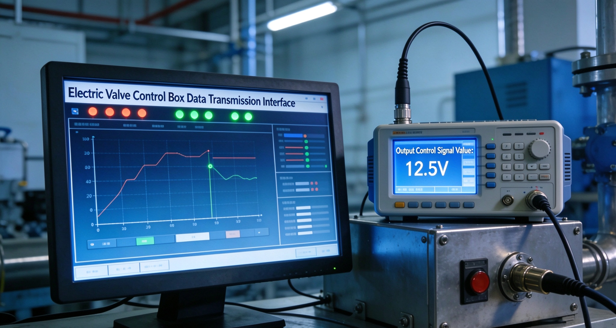
Many electric valve control systems use standardized analog signals for transmitting valve position or process information. Common examples include 4–20 mA and 0–10 V signals.
For a typical 4–20 mA position signal, the current corresponds to a defined operating range. In a simplified configuration, 4 mA may represent 0% and 20 mA may represent 100%, although the exact scaling must always be confirmed from the project configuration.
Technicians can measure the signal using an appropriate meter or signal-testing instrument and compare the measured value with the expected valve position.
For example:
| Valve Position | Typical 4–20 mA Signal |
|---|---|
| 0% | 4 mA |
| 25% | 8 mA |
| 50% | 12 mA |
| 75% | 16 mA |
| 100% | 20 mA |
This table represents a common linear configuration rather than a universal requirement. Some systems use different scaling, characterization, or fail-safe arrangements.
Signal testing should not focus only on whether a measurement falls within an acceptable range. Stability is also important. A fluctuating analog signal may indicate electrical interference, loose terminals, a failing transmitter, poor grounding, damaged wiring, or an unstable power supply.
For industrial control applications, signal integrity can directly affect process control. An inaccurate position signal may cause the PLC or DCS to make inappropriate control decisions, especially in closed-loop modulating applications.
The test should therefore include several valve positions rather than checking only fully open and fully closed conditions. Intermediate positions can reveal calibration errors that remain hidden during simple end-position testing.
Modern electric valve control boxes may communicate with PLCs, DCS platforms, SCADA systems, or other supervisory systems. Communication testing should confirm that commands, status information, alarms, and position data can be exchanged correctly.
The exact communication method depends on the project architecture and may involve industrial communication protocols or dedicated I/O. Regardless of the protocol, technicians should verify that the control system receives accurate information from the valve control box and that commands from the upper-level system reach the actuator correctly.
Communication problems may appear as intermittent disconnections, delayed responses, incorrect status indications, or missing data. These problems can be caused by wiring, connectors, power supply issues, configuration errors, electromagnetic interference, network hardware, or software parameters.
A communication system that works during a short manual test may still experience intermittent problems during continuous operation. Therefore, testing should ideally include a sufficiently long observation period when the application is critical.
Maintenance personnel should monitor communication status, alarm records, response time, and data integrity where these functions are available. Repeated communication interruptions should not automatically be attributed to the control box itself. The entire communication path should be investigated.
This includes the control box, communication cable, connectors, network equipment, power supply, control system configuration, and relevant software settings.
A no-load functional test cannot reveal every potential fault. A control box and actuator should be evaluated under representative operating conditions whenever the maintenance procedure and process safety requirements permit.
During load operation, technicians can observe whether the actuator completes its movement smoothly and whether electrical components remain within acceptable operating conditions. Abnormal current, excessive heat, unusual noise, or repeated protection trips may indicate an underlying mechanical or electrical problem.
Load testing should be performed according to the equipment manufacturer's procedures and the facility's safety requirements. Personnel should never bypass protective devices simply to force an actuator to complete a movement.
Thermal inspection is an effective way to identify electrical connection problems and overloaded components. An infrared thermometer or thermal imaging camera can help identify abnormal temperature differences between similar components.
Particular attention should be given to:
- Contactors
- Relay terminals
- Circuit breakers
- Cable terminals
- Power supplies
- Motor connections
- Transformer connections
- High-current conductors
A localized hot spot may indicate a loose terminal or excessive contact resistance, while widespread heating may indicate overload, insufficient ventilation, or an environmental problem.
Temperature measurements should be interpreted according to the component rating, ambient temperature, load conditions, and manufacturer's specifications. A temperature that appears high in isolation is not necessarily abnormal without considering these factors.
Audible and mechanical observations remain valuable even in highly automated facilities. Relay chatter, repeated contactor switching, actuator vibration, grinding noises, unusual motor sounds, or irregular mechanical movement may indicate developing problems.
For example, frequent relay operation may be associated with unstable control signals, incorrect control logic, or voltage fluctuations. Excessive actuator vibration may be related to mechanical misalignment, mounting problems, valve resistance, or actuator faults.
The objective is to identify changes from normal operating behavior. Establishing a baseline during commissioning can make future condition monitoring significantly more effective.
Loose terminals are among the most common causes of electrical problems in industrial equipment. They can create intermittent signals, voltage drops, localized heating, and eventual component damage.
When a loose connection is suspected, technicians should inspect the relevant terminal, verify conductor condition, and follow the manufacturer's specified tightening requirements. Simply tightening every terminal indiscriminately is not an appropriate substitute for a documented inspection procedure.
Water ingress can lead to corrosion, insulation degradation, short circuits, and electronic component failure. Dust accumulation can reduce heat dissipation and, depending on the material, contribute to tracking or contamination problems.
If moisture or contamination is found inside the enclosure, the source should be identified rather than simply cleaning the components. Possible causes include damaged gaskets, incorrectly installed cable glands, condensation, enclosure pressure changes, or improperly sealed conduit entries.
Overheating may result from excessive actuator load, repeated operation, poor ventilation, high ambient temperature, loose connections, or component degradation. The correct diagnosis requires comparing actual operating conditions with the equipment's rated characteristics.
An electric actuator should not be assumed to be defective simply because its control box becomes warm during operation. Electrical components naturally generate heat, and the important question is whether the temperature remains within the permitted operating range.
Incorrect position feedback can create significant control problems, particularly in modulating applications. The root cause may be a misadjusted limit switch, damaged sensor, mechanical coupling problem, incorrect scaling, or wiring fault.
A useful diagnostic approach is to compare three values: the commanded position, the actual mechanical position, and the feedback value received by the control system. Differences between these values can help narrow down the fault location.
A standardized inspection procedure improves consistency between maintenance technicians and different pieces of equipment. A practical sequence can include the following stages.
Before testing, review the control box nameplate, wiring diagram, actuator manual, valve specifications, control logic, and relevant project requirements. Confirm the rated voltage, current, control signals, communication method, enclosure requirements, and protection functions.
Inspect the enclosure, door, gasket, cable glands, mounting hardware, internal wiring, terminals, and components. Record any corrosion, contamination, overheating marks, deformation, or loose parts.
After applying the facility's required isolation and lockout/tagout procedures, inspect electrical connections and grounding. Appropriate electrical test equipment should be used by qualified personnel following the applicable safety requirements.
Verify local and remote open, close, and stop commands. Confirm correct valve direction and end-position behavior. Check that alarms and protective functions respond as designed.
Measure position feedback and other analog signals at several operating points. Compare measured values with the expected values defined by the control system.
Confirm that the control box communicates correctly with the PLC, DCS, SCADA, or other upper-level system. Monitor for intermittent communication faults where appropriate.
Operate the equipment under representative load conditions and monitor temperature, noise, vibration, current, actuator response, and alarm behavior.
All inspection results should be documented. A useful maintenance record should include measured values, abnormal observations, corrective actions, component replacements, and the final equipment status.
| Item | Inspection Point | Evaluation |
|---|---|---|
| Enclosure | Cracks, deformation, corrosion | Pass / Repair |
| Door seal | Gasket and sealing condition | Pass / Replace |
| Cable entries | Glands and conduit sealing | Pass / Repair |
| Internal wiring | Loose, damaged, or burned wires | Pass / Repair |
| Terminals | Tightness and oxidation | Pass / Repair |
| Input voltage | Compare with rated value | Pass / Investigate |
| Grounding | Protective earth connection | Pass / Investigate |
| Open/close control | Correct actuator response | Pass / Investigate |
| Stop function | Correct stopping response | Pass / Investigate |
| Position feedback | Actual vs displayed position | Pass / Calibrate |
| Protection | Overload and fault response | Pass / Investigate |
| Analog signal | 4–20 mA / 0–10 V | Pass / Investigate |
| Communication | Data transmission and status | Pass / Investigate |
| Temperature | Abnormal hot spots | Pass / Investigate |
| Noise/vibration | Abnormal operating behavior | Pass / Investigate |
Inspection should be part of a preventive or condition-based maintenance strategy rather than an isolated activity performed only after a failure. The frequency should reflect the equipment's criticality, operating environment, switching frequency, historical failure rate, and manufacturer's recommendations.
Control boxes installed outdoors, near corrosive chemicals, in high-humidity areas, or in locations with significant vibration may require more frequent inspection than equipment installed in clean indoor environments.
Maintenance teams can also improve reliability by establishing baseline measurements during commissioning. Baseline values for voltage, current, temperature, feedback signals, and actuator operating time can later be used to identify gradual deterioration.
Trend-based monitoring is particularly valuable because many failures do not occur suddenly. A gradual increase in motor current, increasing terminal temperature, or increasingly unstable feedback signal may provide an early warning before a complete failure occurs.
Electrical control box inspection involves potentially hazardous energy sources. Personnel should follow the facility's electrical safety procedures, equipment isolation requirements, and lockout/tagout practices before opening or testing equipment where required.
Live electrical measurements should only be performed by appropriately trained and authorized personnel using properly rated test instruments and suitable personal protective equipment. Protective devices should never be bypassed simply to determine whether a system can continue operating.
Functional testing should also consider the valve's process role. A valve connected to a pressurized, high-temperature, toxic, corrosive, or otherwise hazardous process may create risks when operated unexpectedly. Before issuing open or close commands, maintenance personnel should understand the consequences of valve movement and coordinate with the relevant operations team.
A control box should not be considered reliable merely because the actuator responds to an open or close command. A comprehensive evaluation should consider the complete relationship between physical condition, electrical integrity, control functionality, signal accuracy, communication reliability, and operating behavior.
The five-dimensional evaluation framework can be summarized as follows:
1. Structural integrity: The enclosure, door, seals, cable entries, internal components, and wiring should be physically sound and appropriately protected against the installation environment.
2. Electrical integrity: Supply voltage, terminals, conductors, protective earth, and electrical components should operate within their specified conditions.
3. Control functionality: Open, close, stop, local, remote, feedback, alarm, and protection functions should respond correctly to their intended commands.
4. Performance accuracy: Analog signals, position feedback, communication data, and other measurable parameters should meet the applicable design requirements.
5. Operating stability: The equipment should operate under representative conditions without abnormal heating, vibration, noise, repeated protection trips, or unstable control behavior.
Electric valve control boxes play a critical role in connecting electrical power, automation systems, and valve actuators. Their reliability directly influences the ability of industrial valves to perform their intended functions safely and consistently. For this reason, evaluating a control box should involve much more than checking whether its indicator lights are working.
A systematic inspection covering enclosure condition, electrical connections, grounding, control functions, position feedback, analog signals, communication performance, temperature, noise, vibration, and load behavior provides a much more complete assessment of equipment health.
For industrial operators, the most effective approach is to combine visual inspection with electrical measurement, functional testing, performance verification, and operating-condition monitoring. When these methods are incorporated into preventive and condition-based maintenance programs, potential problems can be detected earlier, unplanned downtime can be reduced, and the service reliability of the entire electric valve system can be improved.
Ultimately, a well-maintained electric valve control box is not only an electrical enclosure. It is an important part of the automation and safety chain that allows industrial valves to respond accurately to process requirements. A disciplined inspection and evaluation strategy therefore provides an essential foundation for safer, more stable, and more efficient industrial fluid-control operations.
