Advances in Nondestructive Testing Technology for OCTGpipes
Abstract: OCTG pipes are critical components in oil and gas production and are exposed to harsh operating conditions, including high temperatures, high pressures, and corrosive environments. These conditions can cause var ious types of damage, including:
- Corrosion
- Fatigue
- Wear
If left undetected, such damage can lead to tubular failure, serious safety incidents, and significant economic losses. Regular nondestructive testing (NDT) is therefore essential for identifying defects at an early stage and preventing failures. This paper systematically examines the major failure mechanisms and defect characteristics of OCTG pipes, with a focus on the following NDT technologies:
- Ultrasonic testing (UT)
- Magnetic flux leakage (MFL) testing
- Eddy current testing (ECT)
- Infrared thermography (IRT)
For each technology, the paper reviews its underlying physical principles, technical advantages, and current applications. It also discusses suitable detection methods and application strategies for different types of defects. Finally, the paper identifies multimodal data fusion, intelligent inspection systems, and real-time downhole monitoring as key directions for future development. The findings provide a technical reference for selecting and implementing NDT systems for oil well tubular inspection.
OCTG pipes, primarily comprising drill pipes, casings, and tubing, are essential components in oil and natural gas exploration, drilling, and production. Casings support the wellbore and isolate geological formations, while drill pipes transmit torque and axial loads during drilling, and tubing provides a flow path for transporting oil and gas to the surface. These tubulars operate under harsh conditions involving high temperatures, high pressures, and exposure to corrosive media such as carbon dioxide (CO₂) and hydrogen sulfide (H₂S). Consequently, they are susceptible to various forms of damage, including corrosion perforation, fatigue fracture, and wear-induced wall thinning. If left undetected, these defects can progressively develop into catastrophic failures, resulting in substantial economic losses and potentially serious safety and environmental incidents.
Regular non-destructive testing (NDT) is therefore essential for ensuring the integrity and safe operation of OCTG pipes. The main NDT methods currently used for tubular inspection include ultrasonic testing (UT), magnetic flux leakage (MFL) testing, eddy current testing (ECT), and infrared thermography (IRT). By examining the primary failure modes of OCTG pipes and the corresponding defect characteristics, this paper reviews the operating principles and current applications of these four inspection methods. The aim is to provide a technical reference for selecting and applying appropriate NDT methods to detect different types of tubular defects.
Corrosion is a major cause of oil well tubular failure, causing pitting, groove-like surface damage, and, in severe cases, perforation. Depending on the corrosive agent, corrosion is generally classified into CO₂ corrosion, H₂S corrosion, and microbiologically influenced corrosion (MIC). CO₂ dissolves in water to form carbonic acid, which can cause uniform corrosion or localized pitting in steel. Corrosion severity generally increases with CO₂ partial pressure, particularly above 0.2 MPa, while elevated temperatures can accelerate corrosion and aggravate localized pitting. In H₂S-containing environments, hydrogen generated by corrosion can enter the steel, causing hydrogen embrittlement and hydrogen-induced cracking. High-strength drill pipes are particularly susceptible to sulfide stress cracking (SSC), which can lead to premature failure. MIC is primarily associated with sulfate-reducing bacteria (SRB), which generate H₂S under anaerobic conditions. This can promote under-deposit corrosion, resulting in localized material loss and potentially rapid perforation that is difficult to control.
Fatigue failure is a major failure mode of OCTG pipes subjected to cyclic loading. During drilling, drill pipes experience combined cyclic stresses from tension, bending, and torsion. Microcracks tend to initiate and gradually propagate at stress concentration areas, particularly thread roots and upset transition zones. Fatigue failure becomes increasingly likely after (10^6)–(10^8) stress cycles. Typical fatigue fracture surfaces consist of three zones: the fatigue crack initiation zone, the stable crack propagation zone, and the final rapid fracture zone. Improper design of the bending strength ratio at threaded connections can also cause uneven stress distribution and accelerate fatigue failure.
OCTG pipes are also susceptible to wear and mechanical damage during service. In deviated and horizontal wells, friction between the drill pipe and the casing's inner wall or the borehole wall can cause wear and thinning of the drill pipe's outer wall. Meanwhile, drilling fluid carrying solid particles, such as rock cuttings and sand, can cause erosive wear on the pipe's inner wall. Mechanical damage, including gouges and impact marks caused by elevators during tripping operations, can also occur. Although such damage may not cause immediate failure, it can create stress concentrations that accelerate corrosion and fatigue crack initiation and propagation.
Defects in OCTG pipes can be broadly classified into wall-thickness loss, such as that caused by wear or corrosion, and localized defects, such as pits and cracks. Ultrasonic testing (UT) is suitable for measuring wall thickness by analyzing the time of flight of ultrasonic echoes. Localized defects may produce changes in magnetic, electrical, or thermal properties, making magnetic flux leakage (MFL) testing, eddy current testing (ECT), and infrared thermography (IRT) suitable for detecting certain types of defects. Table 1 summarizes the typical defects associated with different failure mechanisms and the corresponding applicable nondestructive testing methods.
Table 1 Failure Modes of OCTG pipes, Typical Defects, and Applicable Inspection Methods
|
Failure Mechanism |
Typical Defects |
Applicable Inspection Methods |
|
CO₂ Corrosion |
Uniform wall thinning, localized corrosion |
UT, MFL, ECT |
|
H₂S Corrosion |
Hydrogen-induced cracking, sulfide stress cracking |
UT, MFL, ECT |
|
Microbiologically Influenced Corrosion |
Under-deposit corrosion, localized pitting |
UT, MFL, ECT |
|
Fatigue |
Surface cracks, fatigue cracks |
UT, MFL, ECT |
|
Wear and Mechanical Damage |
Wall thinning, scratches, dents |
UT, MFL, ECT |
Ultrasonic testing (UT) uses high-frequency sound waves that propagate through a material and reflect from interfaces such as the back wall or defects. An ultrasonic transducer generates the sound waves, and a couplant is generally required to ensure efficient transmission into the material. By analyzing the reflected signals, inspectors can identify defects and measure wall thickness. Figure 1 illustrates the structure of a conventional ultrasonic probe and its typical signal characteristics. Common UT techniques include conventional pulse-echo testing, phased array ultrasonic testing (PAUT), and time-of-flight diffraction (TOFD). In pulse-echo testing, the same transducer transmits and receives the ultrasonic waves, whereas in through-transmission configurations, separate transducers are used for transmission and reception. For OCTG pipes, ultrasonic probes are commonly positioned on the pipe's outer surface.
Ultrasonic waves propagate through solid materials as longitudinal or shear waves and are reflected or scattered when they encounter material discontinuities. The amplitude of the reflected signal depends on factors such as defect size, orientation, and type, as well as the acoustic properties of the materials involved. For example, an air-filled crack can produce strong reflections because of the large acoustic impedance mismatch, whereas a water-filled crack may produce weaker reflections and be more difficult to detect. By analyzing the ultrasonic time of flight and the characteristics of the reflected signals, together with the known sound velocity in the material, inspectors can determine defect locations, estimate defect dimensions, and measure wall thickness.
Ultrasonic phased array (PAUT) technology overcomes a key limitation of conventional single-element probes, which often require physical movement to inspect different areas or angles. Based on wave propagation and interference principles, PAUT uses an array of independently controlled piezoelectric elements with precisely timed excitation delays to steer and focus the ultrasonic beam. This enables electronic scanning and imaging over a larger inspection area with reduced mechanical probe movement.
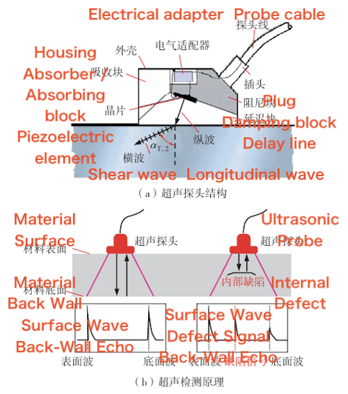
(a) Ultrasonic probe structure (b) Ultrasonic inspection principle
Figure 1. Ultrasonic probe structure and inspection principle
OCTG pipes operate under harsh conditions involving high temperatures, high pressures, and exposure to corrosive media such as H₂S and CO₂. They are susceptible to various defects, including fatigue cracks at threaded connections, corrosion-induced wall thinning, longitudinal and circumferential cracks on the inner and outer surfaces, and stress corrosion cracking. Traditional ultrasonic inspection methods that rely on mechanical scanning with single-element probes are limited by low scanning speeds, coupling difficulties, and limited suitability for online monitoring. These limitations make them less capable of meeting the demands of modern drilling operations and extended tubular service life.
To enable rapid inspection of drill pipes during tripping operations at the wellhead, a wheeled ultrasonic inspection system with dry-coupled probes has been developed. The system uses a multilayer flexible dry-coupling structure to accommodate different drill pipe diameters without requiring an external couplant. It achieves inspection speeds exceeding 0.5 m/s and can detect radial cracks and corrosion pits as shallow as 1 mm, reducing the inspection time per drill pipe at the wellhead to less than 2 minutes. To address inspection blind spots caused by the complex geometry of threaded connections, phased array ultrasonic testing (PAUT) uses 64- or 128-element array probes with electronic scanning and dynamic focusing to generate circumferential images through 360° coverage without mechanical rotation. For fatigue cracks at the thread roots of drill pipe box connections, this technique reportedly provides two to three times the detection sensitivity of conventional UT, with a crack-depth measurement error of less than 0.3 mm. It has also been deployed on offshore platforms.
For real-time corrosion monitoring in long-service tubing, online systems equipped with multi-element ultrasonic sensor arrays use 16 or 32 circumferentially arranged probes to continuously measure wall thickness at multiple locations. With a measurement accuracy of ±0.05 mm, these systems can track corrosion rates ranging from 0.1 to 2.5 mm/year and provide early warnings of accelerated wall thinning. To detect sulfide stress cracking (SSC) in drill pipes used in ultra-deep, high-sulfur wells, high-resolution electromagnetic acoustic transducer (EMAT) technology generates multimode shear waves at temperatures of up to 300°C without requiring a couplant. This enables quantitative measurement of crack depth and length, with reported errors of less than 0.5 mm, as well as the detection of coating disbondment. In addition, multimode tandem ultrasonic testing combines eight probe configurations using longitudinal and shear waves to reduce the influence of circumferential defect orientation, increasing the detection rate for inner-wall defects from 65% to more than 95%. Figure 2 shows typical piezoelectric ultrasonic signals obtained during drill pipe defect inspection.
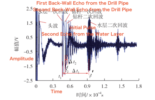
Figure 2. Typical Piezoelectric Ultrasonic Signals for Drill Pipe Defect Detection
Ultrasonic testing (UT) is a key inspection technology for OCTG pipes, offering high-precision wall thickness measurement and internal defect detection. The introduction of phased array ultrasonic testing (PAUT) has advanced UT from point-by-point inspection to area imaging, substantially improving inspection coverage. However, conventional UT remains dependent on effective acoustic coupling, while inspection efficiency can be limited by mechanical scanning speed. Current research therefore focuses on techniques such as dry-coupled UT and electromagnetic acoustic transducer (EMAT) technology to reduce coupling requirements and broaden the application of ultrasonic inspection.