Rising Stem vs. Non-Rising Stem Gate Valves
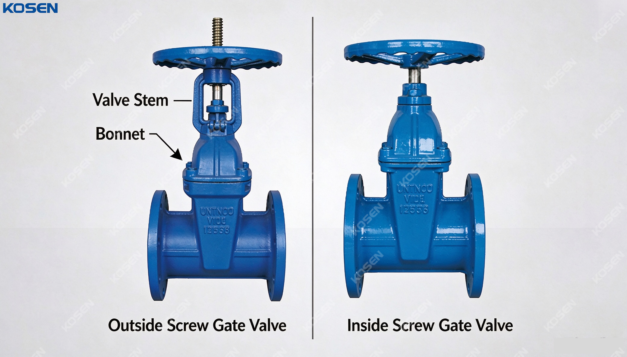
Gate valves are among the most widely used isolation valves in industrial and municipal piping systems. They are commonly installed where the primary requirement is to fully open or fully close a pipeline rather than continuously regulate flow. Water treatment plants, oil and gas facilities, power stations, chemical processing plants, fire protection systems, and general industrial piping all rely on gate valves for dependable isolation.
Although gate valves may appear similar from the outside, their internal and operating configurations can differ significantly. One of the most important design choices is the relationship between the valve stem and the valve body. This distinction creates two major configurations: the rising stem gate valve, commonly called an OS&Y or outside screw and yoke gate valve in many applications, and the non-rising stem gate valve, in which the stem remains within the valve body while the gate moves internally.
The difference is not merely a matter of appearance. Stem configuration affects valve position indication, installation space, environmental exposure, maintenance accessibility, corrosion protection, operating characteristics, and lifecycle costs. Therefore, selecting between a rising stem and non-rising stem design requires more than comparing purchase prices.
The correct choice should be based on the actual service conditions, available installation space, maintenance philosophy, safety requirements, and applicable standards.
A gate valve controls flow by moving a gate or wedge perpendicular to the direction of fluid flow. When the valve is fully open, the gate is lifted away from the flow passage, creating a relatively unobstructed path. When the valve is closed, the gate moves into the sealing position and isolates the downstream section.
A typical gate valve consists of several major components:
- Valve body
- Bonnet
- Gate or wedge
- Valve stem
- Seat rings
- Stem packing
- Handwheel, gearbox, or actuator
- Bonnet gasket
- Bolting or other pressure-retaining connections
The exact configuration varies according to the valve design, pressure class, material, size, and applicable standard.
Gate valves are generally intended for isolation service rather than throttling. Using a gate valve partially open for prolonged periods can create undesirable flow conditions, including vibration, erosion, noise, and damage to sealing surfaces. For applications requiring continuous flow regulation, globe valves, control valves, or other suitable throttling designs are normally considered.
A non-rising stem gate valve, commonly referred to as an NRS gate valve, uses a stem that does not visibly move upward or downward as the valve opens and closes. Instead, the stem rotates while the gate moves internally through a threaded connection or another mechanical arrangement.
Because the stem remains within the overall valve envelope, the external height of the valve remains relatively compact during operation. This makes the configuration particularly useful where vertical clearance is limited.
NRS gate valves are widely used in municipal water systems, underground pipelines, water treatment facilities, fire protection systems, and other installations where compact dimensions and protected operating components are important.
In a typical NRS design, rotation of the handwheel or operating nut causes the threaded stem to move the gate along the valve's internal guide structure. The operator therefore rotates the operating component without seeing a corresponding vertical movement of the stem.
This design provides a compact external configuration, but it also creates an important operational limitation: the position of the gate cannot always be determined simply by looking at the stem.
Operators may therefore need a position indicator or other method of confirming whether the valve is fully open or fully closed, particularly in systems where incorrect valve positioning could create operational or safety problems.
A rising stem gate valve uses a stem that moves vertically as the valve is operated. Depending on the design, the stem may rise while the handwheel remains in a fixed vertical position, or the handwheel and stem may rise together.
The rising stem configuration is commonly associated with outside screw and yoke (OS&Y) gate valves. As the valve is opened, the visible stem extends upward; as it is closed, the stem moves downward.
This physical movement provides a simple and highly visible indication of valve position.
One of the most important advantages of a rising stem design is that operators can generally identify the approximate valve position from the stem position.
A fully extended stem typically indicates an open valve, while a retracted stem indicates a closed valve. This characteristic is especially valuable in facilities with many valves where operators need to identify valve status quickly.
For fire protection systems and certain industrial installations, this visibility can support operational control and inspection activities. However, visual indication should still be combined with proper valve labeling, operating procedures, and system documentation rather than being treated as the only method of confirming valve status.
The most fundamental difference can be summarized as follows:
| Feature | Non-Rising Stem Gate Valve | Rising Stem Gate Valve |
|---|---|---|
| Stem movement | Rotates without external vertical movement | Moves vertically during operation |
| External height | Relatively compact | Requires additional vertical clearance |
| Valve position visibility | Less direct | Highly visible |
| Stem exposure | Mostly protected inside valve body | Exposed above valve body |
| Installation space | Suitable for restricted vertical space | Requires sufficient overhead clearance |
| Maintenance access | Internal mechanism may be less accessible | Stem and operating mechanism are generally easier to inspect |
| Environmental exposure | Lower external stem exposure | Greater external stem exposure |
| Common applications | Underground water, municipal systems | Industrial plants, fire protection, process facilities |
| Position monitoring | May require indicator | Often visually apparent |
| Maintenance philosophy | Compact but internal access can be more involved | Easier external inspection |
This comparison does not mean that one configuration is universally better. Instead, each design solves a different engineering problem.
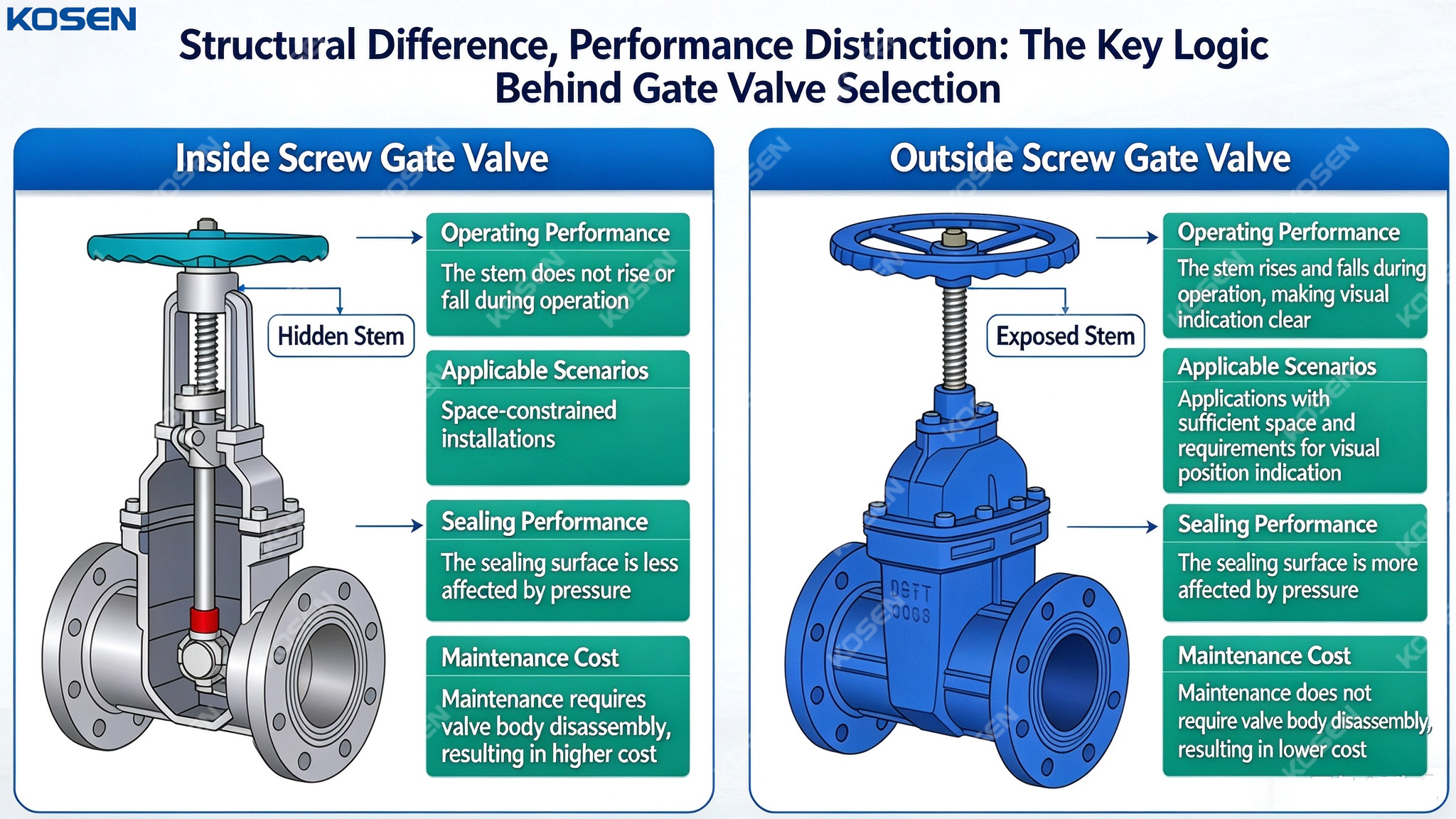
Valve position is an important consideration in any isolation system. An incorrectly positioned valve can interrupt water supply, prevent equipment isolation, reduce process availability, or interfere with emergency response.
Rising stem valves offer an inherent mechanical indication because the stem position changes visibly. This is particularly useful when operators need to inspect multiple valves quickly.
Non-rising stem valves can still provide reliable position information, but additional indicators may be required depending on the valve design and application. In underground installations, for example, operators may rely on operating indicators, extension stems, valve boxes, or other mechanical position-monitoring arrangements.
For critical systems, the valve position should be confirmed using the appropriate inspection and control method rather than assuming that the handwheel position alone provides sufficient information.
Installation geometry is one of the clearest areas where the two configurations differ.
A non-rising stem gate valve maintains a relatively stable external height as the valve is operated. This can be advantageous in underground chambers, valve pits, equipment rooms with low ceilings, and installations where overhead clearance is restricted.
A rising stem gate valve requires sufficient vertical space for the stem to extend. Engineers therefore need to consider the maximum operating height, not merely the valve's initial dimensions.
Before specifying a rising stem valve, the engineering team should evaluate:
- Is there enough vertical clearance above the valve?
- Could structural beams interfere with stem movement?
- Is there sufficient space for handwheel or gearbox operation?
- Can maintenance personnel safely access the stem?
- Could the extended stem interfere with walkways or equipment?
- Will insulation or other components restrict movement?
These considerations are particularly important in densely packed industrial facilities.
The valve stem is an important mechanical component, and its operating condition directly affects valve reliability. In a rising stem design, part of the stem is exposed to the surrounding environment during operation.
In outdoor installations, the stem may encounter rain, dust, salt-laden air, industrial pollutants, ultraviolet exposure, or mechanical impact. In corrosive environments, these factors can accelerate deterioration if the stem material and protective system are not properly selected.
Non-rising stem designs place more of the stem mechanism inside the valve body. This can provide useful protection in certain environments, particularly underground or outdoor water applications.
However, it would be inaccurate to conclude that every NRS valve is automatically more corrosion-resistant or that every rising stem valve is vulnerable to corrosion. Stem material, coatings, bonnet protection, packing design, lubrication, environmental conditions, and maintenance practices all influence actual performance.
The original assumption that non-rising stem valves inherently provide better sealing requires qualification.
Internal sealing and external stem sealing are influenced by multiple design factors. A gate valve's ability to isolate the pipeline depends on the gate-seat interface, seat design, material selection, pressure conditions, manufacturing tolerances, and the condition of the sealing surfaces.
External leakage around the stem is primarily related to the packing system and stem condition. Rising stem designs expose more of the stem to the environment, but properly designed packing and stem protection can provide reliable sealing over long service periods.
Therefore, when comparing sealing performance, engineers should examine the complete valve design rather than selecting a stem configuration solely because of assumptions about leakage.
Maintenance accessibility is another important distinction.
A rising stem valve generally provides easier visual access to the stem, yoke, handwheel, gearbox, and packing area. Operators can inspect the stem condition without opening the pressure boundary.
If corrosion, mechanical damage, packing deterioration, or abnormal movement is detected, maintenance personnel can often address the issue without completely dismantling the valve.
A non-rising stem design protects the operating mechanism inside the valve, but inspection of internal components may require more extensive intervention if a mechanical problem develops.
For both valve types, maintenance programs may include:
- Checking operating torque.
- Inspecting the stem and packing.
- Checking for external leakage.
- Inspecting handwheels and gearboxes.
- Confirming full opening and closing.
- Removing accumulated dirt or corrosion.
- Checking bolts and bonnet connections.
- Inspecting internal sealing components when required.
- Lubricating components where the manufacturer specifies lubrication.
- Recording operating and repair history.
Maintenance requirements should always follow the valve manufacturer's instructions and the applicable project standards.
Corrosion is a particularly important issue for valves installed outdoors, underground, offshore, coastal, or in chemically aggressive environments.
For rising stem valves, the exposed portion of the stem should be made from an appropriate material or provided with suitable protection. Stainless steel stems, protective coatings, stem covers, and appropriate packing arrangements may be used depending on the service.
For non-rising stem valves, internal components may be exposed to the pipeline medium. Therefore, corrosion resistance still depends heavily on material compatibility.
This distinction is important: protecting the stem from external weather does not eliminate the need to evaluate the internal fluid environment.
Municipal water networks are one of the most common application areas for non-rising stem gate valves. Underground valve chambers often have strict dimensional limitations, and the valve may need to remain below grade.
A compact NRS configuration avoids the need for a long externally rising stem. The operating mechanism can be accessed through a valve box or extension arrangement.
Water systems also commonly benefit from resilient-seated gate valve designs that provide reliable shutoff under suitable operating conditions. However, the valve still needs to be selected according to water quality, pressure, temperature, installation conditions, and applicable water industry standards.
Industrial process facilities often place greater emphasis on visible valve position, inspection accessibility, and operational control. In these environments, rising stem gate valves can offer practical benefits.
Operators can identify valve position from a distance, and maintenance personnel can inspect the exposed operating mechanism. This can be especially useful in facilities with complex process lines where many isolation valves are located close together.
In fire protection systems, OS&Y gate valves are also widely recognized because the stem position provides a direct indication of whether the valve is open or closed. Specific fire protection applications should, however, use valves that comply with the applicable certification and system requirements.
Stem configuration should never be selected independently of pressure and temperature requirements.
A valve must be capable of safely handling the maximum operating pressure, design pressure, temperature range, and relevant transient conditions. Common industrial gate valve specifications may reference standards such as API 600, API 602, ASME B16.34, or other applicable standards depending on the valve type and application.
Material selection is equally important. Carbon steel, stainless steel, alloy steel, ductile iron, cast iron, and other materials are used for different applications.
For example, a carbon steel valve may be suitable for many industrial services, while stainless steel may be preferred where corrosion resistance is more important. Water distribution systems may use ductile iron valves because of their mechanical properties and established application history.
Valve selection must also account for the pipeline's connection and pressure requirements.
Industrial gate valves may use flanged, threaded, socket-weld, or butt-weld ends depending on size and application. Flanged valves are common in many industrial systems because they can be removed for maintenance without cutting the pipeline.
Pressure classes such as Class 150, 300, 600, and higher are used in many ASME-based industrial systems. Other markets use PN pressure designations under different standards.
The pressure rating should never be inferred simply from nominal pipe size. Engineers need to verify the complete pressure-temperature rating of the selected valve material and design.
Stem configuration is only one part of gate valve selection. The internal gate design also matters.
Wedge gate valves use a wedge-shaped gate that engages with angled seats. This configuration can provide effective shutoff and is widely used in industrial isolation service.
Parallel gate valves use parallel sealing surfaces and may employ different internal mechanisms depending on the design. They can be advantageous in particular process conditions and specialized services.
The choice between wedge and parallel designs should be based on pressure conditions, thermal behavior, fluid characteristics, required shutoff performance, and the manufacturer's design specifications.
One common selection mistake is using a gate valve as a permanent flow-control device.
When partially open, the gate can create high local velocities and turbulent flow around the sealing components. This can increase erosion, vibration, noise, and damage to the gate and seats.
Gate valves are generally better suited to fully open or fully closed service. If a process requires continuous modulation of flow, a properly sized control valve or another valve type designed for throttling should normally be considered.
This distinction can have a major influence on valve service life.
The initial purchase price is only one component of valve economics. A lower-cost valve may become more expensive over its service life if it requires frequent maintenance, suffers from corrosion, has poor accessibility, or causes operational difficulties.
A lifecycle assessment should consider:
| Cost Category | Rising Stem Gate Valve | Non-Rising Stem Gate Valve |
|---|---|---|
| Initial cost | Depends on material and configuration | Depends on material and configuration |
| Space requirement | Higher vertical clearance | More compact |
| Position visibility | Generally high | May require indicator |
| External stem protection | Requires attention | Less externally exposed |
| Maintenance access | Generally convenient | Can be more involved internally |
| Underground installation | Less convenient in many cases | Often advantageous |
| Industrial plant use | Frequently suitable | Suitable in space-constrained applications |
| Long-term cost | Depends on service and maintenance | Depends on service and maintenance |
There is therefore no universal cost winner. The appropriate valve is the one that minimizes total lifecycle cost under the actual application conditions.
Engineers can simplify the decision by evaluating the application in a defined sequence.
Identify the fluid, flow direction, operating pressure, temperature, solids content, corrosiveness, and required shutoff performance.
Determine whether the valve is above ground, underground, indoors, outdoors, in a valve chamber, or in a restricted-access location.
Measure both horizontal and vertical clearance. Do not evaluate only the installed valve dimensions. Consider the full operating envelope.
If rapid visual confirmation of valve position is important, a rising stem configuration may provide practical advantages. If the valve is underground or inaccessible, an appropriate position indicator may be necessary regardless of stem type.
Consider how often the valve will be operated, how easily technicians can access it, and whether the facility has sufficient space for repair and replacement.
Match the body, stem, gate, seat, packing, and other components to the medium, temperature, pressure, and environmental conditions.
Confirm the relevant design, testing, connection, fire protection, drinking water, or project-specific requirements before finalizing the specification.
Several recurring mistakes can undermine otherwise well-designed piping systems.
A DN200 or 8-inch valve is not adequately specified simply because its nominal size matches the pipeline. Pressure class, material, end connection, seat design, and operating conditions must also be defined.
Selecting a rising stem valve without checking the maximum stem extension can create installation conflicts.
A compact non-rising stem design may be appropriate, but critical applications still require reliable methods of determining valve status.
An outdoor valve exposed to rain, dust, salt spray, or industrial chemicals requires appropriate material and protective measures.
This can shorten valve life and damage the sealing surfaces.
Two gate valves with the same nominal size may have significantly different materials, pressure ratings, sealing systems, standards, and service capabilities.
Modern industrial facilities increasingly use digital asset management and condition-based maintenance to improve valve reliability. Stem position sensors, actuator feedback, smart monitoring devices, and computerized maintenance management systems can provide additional operational information.
For automated rising stem valves, position feedback can be integrated into the control system. Non-rising stem valves can also be equipped with suitable position indicators or sensors depending on the design.
Digital monitoring does not replace correct mechanical design, but it can improve visibility and help maintenance teams identify abnormal operation before a valve failure affects the process.
The difference between rising stem and non-rising stem gate valves is fundamentally a difference in mechanical configuration, but its consequences extend into operation, installation, inspection, maintenance, and lifecycle cost.
A non-rising stem gate valve offers a compact configuration and can be highly suitable for underground water networks, valve chambers, and applications where vertical space is limited. Its protected stem arrangement can also reduce exposure to certain external environmental conditions.
A rising stem gate valve, particularly an OS&Y design, provides clear visual indication of valve position and generally offers convenient access to external operating components. These characteristics make it useful in many industrial facilities and applications where valve status and maintenance accessibility are important.
However, stem configuration should never be treated as the sole selection criterion. Reliable valve performance depends on the complete combination of valve design, pressure rating, materials, sealing system, installation conditions, operating environment, fluid characteristics, and maintenance strategy.
The most effective selection logic is therefore not simply to ask, "Which valve is better?" Instead, engineers should ask, "Which valve configuration best matches the service conditions, installation environment, operational requirements, and lifecycle objectives of this particular system?"
When that question is answered systematically, rising stem and non-rising stem gate valves can each provide reliable isolation performance. Proper selection at the design stage can reduce installation problems, simplify maintenance, improve operational safety, extend valve service life, and deliver better overall value throughout the lifecycle of the piping system.
