Heat Exchanger Tube Failure Analysis and Crack Prevention Strategies
Abstract: Cracking of heat exchanger tubes is a significant challenge in industrial applications. This study investigates intergranular stress corrosion cracking (IGSCC) in S31603 stainless steel heat exchanger tubes resulting from the combined effects of residual stress and corrosive media containing phosphorus, sulfur, and fluorine. Based on the identified failure mechanisms, a five-dimensional prevention framework is proposed, encompassing five key aspects:
- Materials: Material selection and performance optimization.
- Manufacturing: Manufacturing process control.
- Environment: Control of corrosive operating conditions.
- Inspection: Detection and monitoring of potential damage.
- Management: Implementation of preventive maintenance and operational controls.
Targeted preventive measures are proposed to mitigate cracking, enhance the operational reliability of heat exchanger tubes, and extend their service life in industrial applications.
In industries such as petrochemicals, power generation, nuclear energy, and metallurgy, heat exchanger tubes are critical components of heat transfer systems, enabling heat exchange between process media and supporting efficient energy conversion. Their reliability directly affects equipment safety, operational stability, production efficiency, and operating costs. S31603 stainless steel is widely used in heat exchanger applications because of its excellent corrosion resistance, good mechanical properties, and workability.
However, during long-term service, heat exchanger tubes are exposed to demanding operating conditions, including high temperatures and pressures, corrosive media, and cyclic loading, which can result in localized stress concentrations. These conditions can cause various forms of damage, including wear, corrosion, and fatigue, ultimately leading to cracking and failure. Such failures can significantly reduce heat transfer efficiency and disrupt production. In more severe cases, tube rupture may cause process fluid leakage, fires, or explosions, resulting in substantial economic losses and adverse social consequences. Therefore, investigating the mechanisms responsible for heat exchanger tube cracking and developing effective preventive measures are essential for improving equipment reliability and ensuring safe operation.
Researchers worldwide have conducted extensive investigations into heat exchanger tube failures. Through techniques such as macroscopic examination, chemical composition analysis, mechanical property testing, and microstructural characterization, they have identified the causes of common failure modes, including corrosion fatigue, stress corrosion cracking (SCC), intergranular corrosion, and welding defects.
However, as industrial equipment is designed to operate at higher pressures and temperatures, over longer service periods, and under increasingly complex conditions, heat exchanger tubes are exposed to more demanding service environments. Their failure mechanisms often involve multiple interacting factors and remain poorly understood under certain operating conditions. Existing preventive measures also have limitations in terms of applicability and effectiveness. In particular, further systematic investigation is needed into crack propagation behavior, microstructural damage evolution, and the interactions among key influencing factors in S31603 stainless steel heat exchanger tubes exposed to complex corrosive environments and mechanical stresses.
This study investigates cracked S31603 stainless steel heat exchanger tubes using a range of analytical techniques, including macroscopic examination, chemical composition analysis, mechanical property testing with particular emphasis on tensile properties, metallographic analysis, and scanning electron microscopy (SEM). These techniques are used to characterize the microstructure of the failed tubes, trace crack propagation paths, and identify the composition of corrosion products. The aim is to determine the root causes and underlying mechanisms of tube cracking, identify the key contributing factors, and propose targeted measures for structural improvement, material selection, and corrosion protection. The findings are expected to provide a sound theoretical basis and practical engineering guidance for enhancing the operational reliability of heat exchanger tubes, extending their service life, and reducing the risk of failure.
The S31603 stainless steel heat exchanger tube examined in this study measures Φ25 × 2 × 6,000 mm and is a typical austenitic stainless steel tube widely used in industrial applications. Its manufacturing process involves several stages. The raw material is first cut and cold-rolled to refine its microstructure and improve its mechanical properties. The tubes are then cut to the required length and degreased before annealing to relieve residual stresses introduced during processing. The tubes are subsequently straightened to ensure dimensional accuracy and pickled to remove surface impurities and improve surface quality. The tube ends are then prepared for assembly. Before cold drawing, the tubes are lubricated to reduce friction during deformation. Cold drawing further improves dimensional accuracy and surface finish. After drawing, the tubes undergo another round of cutting, degreasing, and annealing, followed by straightening, final trimming, and pickling. Strict process control is maintained throughout the manufacturing process to ensure that the finished tubes meet the relevant technical requirements.
The heat exchanger assembly process involves several key steps. Upon delivery, the tubes are inspected to verify that they meet applicable industry standards and design requirements before installation. During tube insertion, each tube is carefully positioned in its corresponding hole in the tube sheet. The tube ends are then faced to achieve the required alignment with the tube sheet surface. Welding and tube expansion are critical operations for securing the tubes to the tube sheet. Welding provides mechanical strength at the joints, while tube expansion enhances the sealing performance of the tube-to-tube-sheet connections and helps prevent process fluid leakage.
The equipment was delivered in July 2024. However, cracks in the heat exchanger tubes were not discovered until April 2025, when the circulating water system was commissioned and flushed. This type of heat exchanger tube is a well-established, mass-produced product, and no similar cracking incidents had previously been reported. The extensive cracking observed in this case therefore suggests that the damage may have occurred during equipment storage or system commissioning after delivery. Further failure analysis is needed to identify the specific causes and contributing factors.
To systematically investigate the causes of heat exchanger tube cracking, a series of tests was conducted on the failed samples using advanced testing equipment and carefully designed experimental procedures. Fractographic examination was a key part of the failure analysis. Macroscopic examination was first performed using the naked eye or a magnifying glass to observe and document key features, including the overall fracture morphology, crack distribution, and propagation direction. These observations provided an initial understanding of the failure characteristics. Microscopic examination was then conducted in accordance with JY/T 0584-2020 and GB/T 17359-2023 using an FEI Quanta 400 scanning electron microscope (SEM) equipped with an EDAX energy-dispersive X-ray spectrometer (EDS). In addition, a ZEISS Imager M2m metallurgical microscope was used to examine the microstructure of the heat exchanger tubes in accordance with GB/T 13298-2015.
Chemical composition analysis and tensile testing were also conducted to investigate the causes of failure by evaluating the material composition and mechanical properties, respectively. Chemical composition analysis was performed in accordance with GB/T 2023-2006 and GB/T 11170-2008 using a CS901B infrared carbon and sulfur analyzer and an ARL 4460 optical emission spectrometer. These instruments were used to determine the chemical composition of the heat exchanger tubes. Tensile testing was conducted in accordance with GB/T 228.1-2021 using a Zwick Z250 universal testing machine to determine key mechanical properties of the heat exchanger tube samples, including tensile strength, yield strength, and elongation after fracture. The intergranular corrosion test was conducted in accordance with GB/T 4334-2020 to evaluate the susceptibility of the tube samples to intergranular corrosion under specified test conditions and assess its potential contribution to tube cracking. The FEI Quanta 400 scanning electron microscope provides detailed images of material microstructures and surface features. The Zwick Z250 tensile testing machine uses a servo motor to drive the crosshead through a reduction gearbox and ball screw mechanism, thereby applying the tensile load. A load cell measures the applied force, while an encoder records crosshead displacement through the rotation of the lead screw. The resulting load and displacement data are used to generate stress-strain curves and evaluate the mechanical properties of the material. The instrument's high measurement precision and advanced technical features help ensure the accuracy and reliability of the test results.
Figure 1(a) shows the overall macroscopic appearance of the heat exchanger tube, with the cracking site marked as 1#. Figure 1(b) provides a closer view of the crack at this location. The sample taken from this site was selected for further examination. Its outer surface, end face, and inner surface are shown in Figures 1(c), 1(d), and 1(e), respectively. As shown in Figures 1(c)–1(e), cracks are clearly visible on the sample. The crack morphology on the outer surface is similar to that observed on the end face, with both extending inward from the tube end. On the inner surface, corrosion-related cracks exhibit considerable variations in depth and width across different regions. Some have penetrated the entire tube wall, forming through-wall cracks. Based on these macroscopic observations, the cracking of the heat exchanger tube is preliminarily considered to be associated with corrosion and stress.
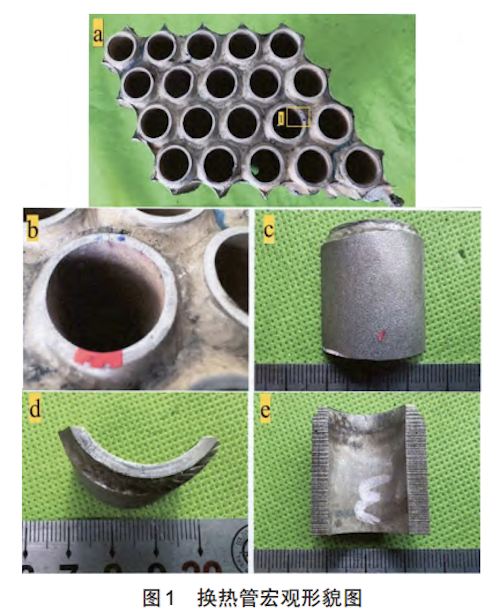
Figure 1. Macroscopic Appearance of the Heat Exchanger Tube
The cross-sectional metallographic specimen shown in Figure 2(b) was etched using a chemical reagent and examined under a metallurgical microscope. A longitudinal specimen was also sectioned from sample 2#, as shown in Figure 3(a), and examined after mounting, grinding, polishing, and chemical etching. As shown in Figures 2(a)–2(c), the microstructure consists of austenite. No obvious microstructural abnormalities were observed in either the weld or the base metal, as shown in Figure 3(b-1).
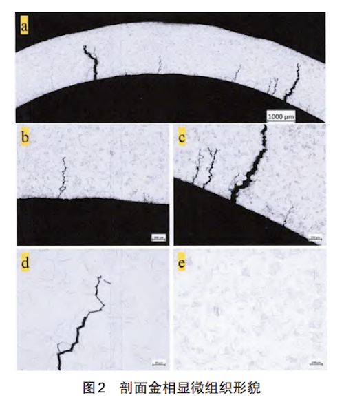
Figure 2. Cross-Sectional Microstructure
Sample 1# was examined using a scanning electron microscope (SEM). The SEM image of the inner surface is shown in Figure 4(a). At higher magnification, the crack exhibits distinct intergranular features, while intergranular corrosion cracks are also visible on the inner surface, as shown in Figure 4(b-1). The specimen containing the crack was sectioned as shown in Figure 5(a), with the end face serving as the observation surface. After mounting and polishing, the specimen was examined using a scanning electron microscope (SEM). The SEM image is shown in Figure 5(b). At higher magnification, the crack can be seen to originate from the inner surface and propagate along the grain boundaries. Dense foreign material is also visible within the crack. The SEM image is shown in Figure 5(c-1). EDS analysis of the foreign material revealed the presence of the corrosive elements fluorine, phosphorus, and sulfur, as shown in Figures 6(a)–6(c). The detection of these elements further indicates that the heat exchanger tube was exposed to corrosive media, with corrosion initiating at the inner surface. The presence of intergranular cracks and dense foreign material within the cracks may compromise the structural integrity of the heat exchanger tube.
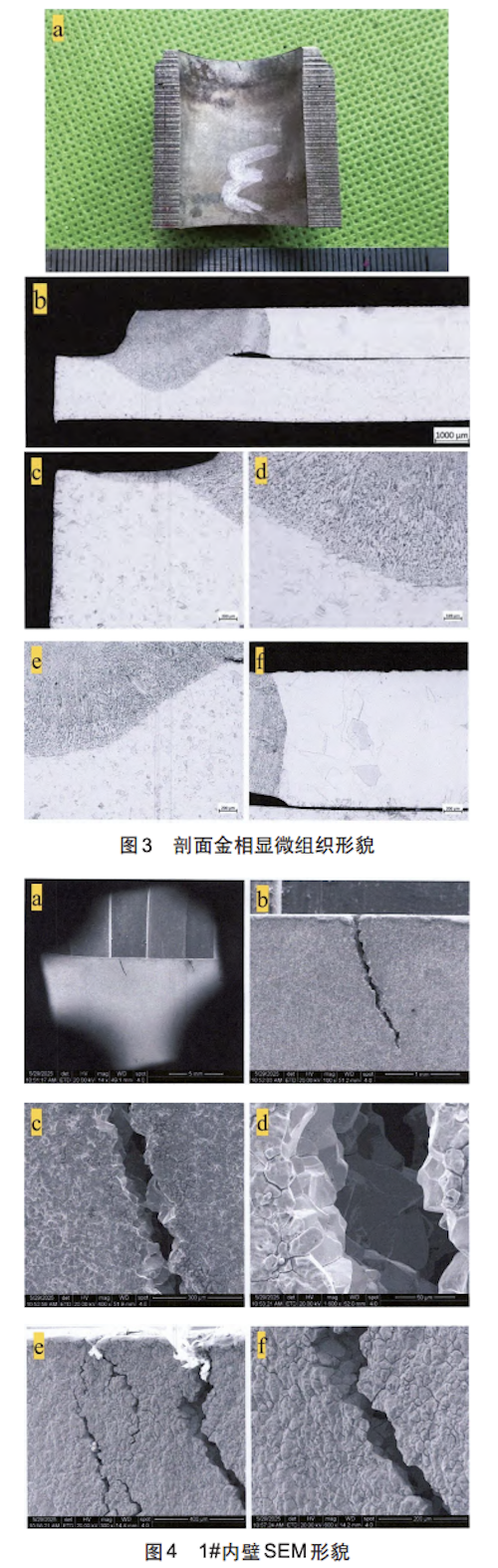
Figure 3. Cross-Sectional Microstructure
Figure 4. SEM Image of the Inner Surface of Sample 1#
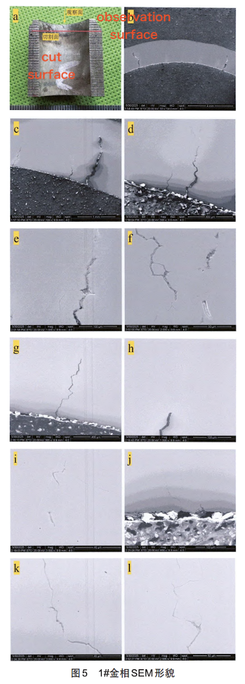
Figure 5. SEM Images of the Metallographic Specimen from Sample 1#
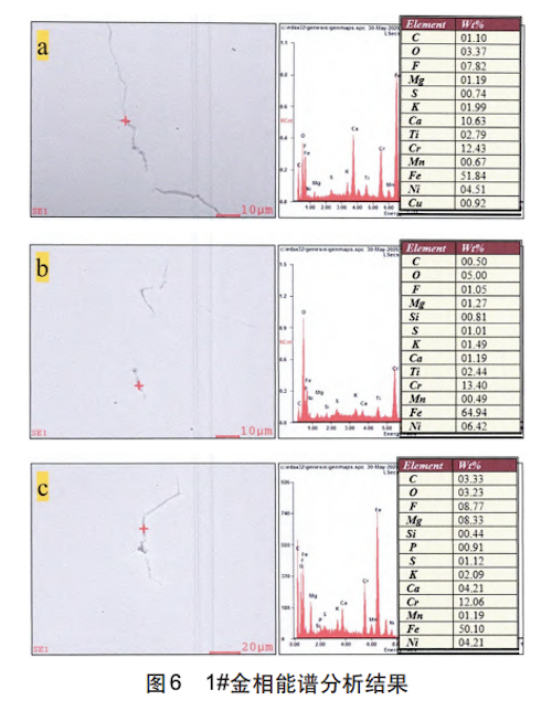
Figure 6. EDS Analysis Results for Sample 1#
As shown in Figures 7(a) and 7(b), specimens were taken from the cracked tube (sample 1#) and two nearby tubes (samples 2# and 3#), with all sampling locations away from the welds. The specimens were tested for intergranular corrosion in accordance with Method E of GB/T 4334-2020 after sensitization at 650°C for 2 h. After acid etching and bending, intergranular corrosion cracks were observed in samples 1# and 3#, as shown in Figures 8(a)–8(c) and Figures 9(a)–9(c), respectively, whereas no cracks were observed in sample 2#. These results indicate that some of the tubes are susceptible to intergranular corrosion under certain environmental conditions, suggesting that intergranular corrosion may be one of the contributing factors to heat exchanger tube cracking and failure.
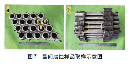
Figure 7. Sampling Locations for the Intergranular Corrosion Test Specimens
The test results indicate that heat exchanger tube cracking results from multiple contributing factors. Among these, the combined effects of welding residual stress and corrosive media are considered the primary cause of stress corrosion cracking (SCC). During welding of the heat exchanger tubes to the tube sheet, localized heating causes the weld region to undergo rapid heating and cooling cycles. Uneven heat input generates thermal stresses in the weld region, which can lead to plastic deformation when the stresses exceed the material's yield strength. After welding, temperature gradients during cooling cause nonuniform shrinkage in the weld region, resulting in significant residual stresses. These stresses remain in the material after cooling and contribute to stress corrosion cracking.
SEM observations and EDS analysis revealed the presence of phosphorus, sulfur, and fluorine in the foreign material found within the cracks. These elements may react with the metal to form corrosion products. Their accumulation along the grain boundaries weakens grain boundary cohesion and reduces the material's strength. Under the influence of welding residual stress, stress concentrations at the grain boundaries become more pronounced, making the heat exchanger tube more susceptible to intergranular cracking. Over time, these cracks can progressively propagate and eventually lead to tube failure.
The metallographic examination revealed an austenitic microstructure, with no obvious microstructural abnormalities in either the weld or the base metal. However, microscopic defects or nonuniform elemental distributions may still be present, making the material susceptible to intergranular corrosion in corrosive environments. The intergranular corrosion test results further demonstrated susceptibility to intergranular corrosion in some of the tested tubes. This corrosion can weaken grain boundaries and promote stress corrosion cracking, making it a major contributing factor to premature cracking and failure of the heat exchanger tubes.
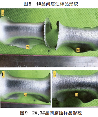
Figure 8. Intergranular Corrosion Morphology of Sample 1#
Figure 9. Intergranular Corrosion Morphology of Samples 2# and 3#
To reduce the susceptibility of stainless steel to intergranular corrosion, appropriate heat treatment and alloy composition optimization should be considered. Proper heat treatment can improve microstructural stability, while the addition of strong carbide-forming elements, such as titanium (Ti) and niobium (Nb), can promote the formation of stable carbides by preferentially combining with carbon. This helps prevent chromium carbide precipitation at grain boundaries, thereby minimizing chromium-depleted zones and improving resistance to intergranular corrosion. Furthermore, quality control should be strengthened throughout the equipment life cycle through random inspections of raw materials and intergranular corrosion testing. During service, the tube surfaces should be examined by scanning electron microscopy (SEM) at six-month intervals, and the corrosion rate should be monitored online to identify potential problems at an early stage.